1-10
Catalyst 3550 Switch Hardware Installation Guide
OL-6155-01
Chapter 1 Product Overview
Rear-Panel Description
Figure 1-7 Bandwidth Utilization for the Catalyst 3550-48
Figure 1-8 shows the bandwidth utilization percentages displayed by the LEDs on the
Catalyst 3550-24-FX switch.
Figure 1-8 Bandwidth Utilization for the Catalyst 3550-24-FX
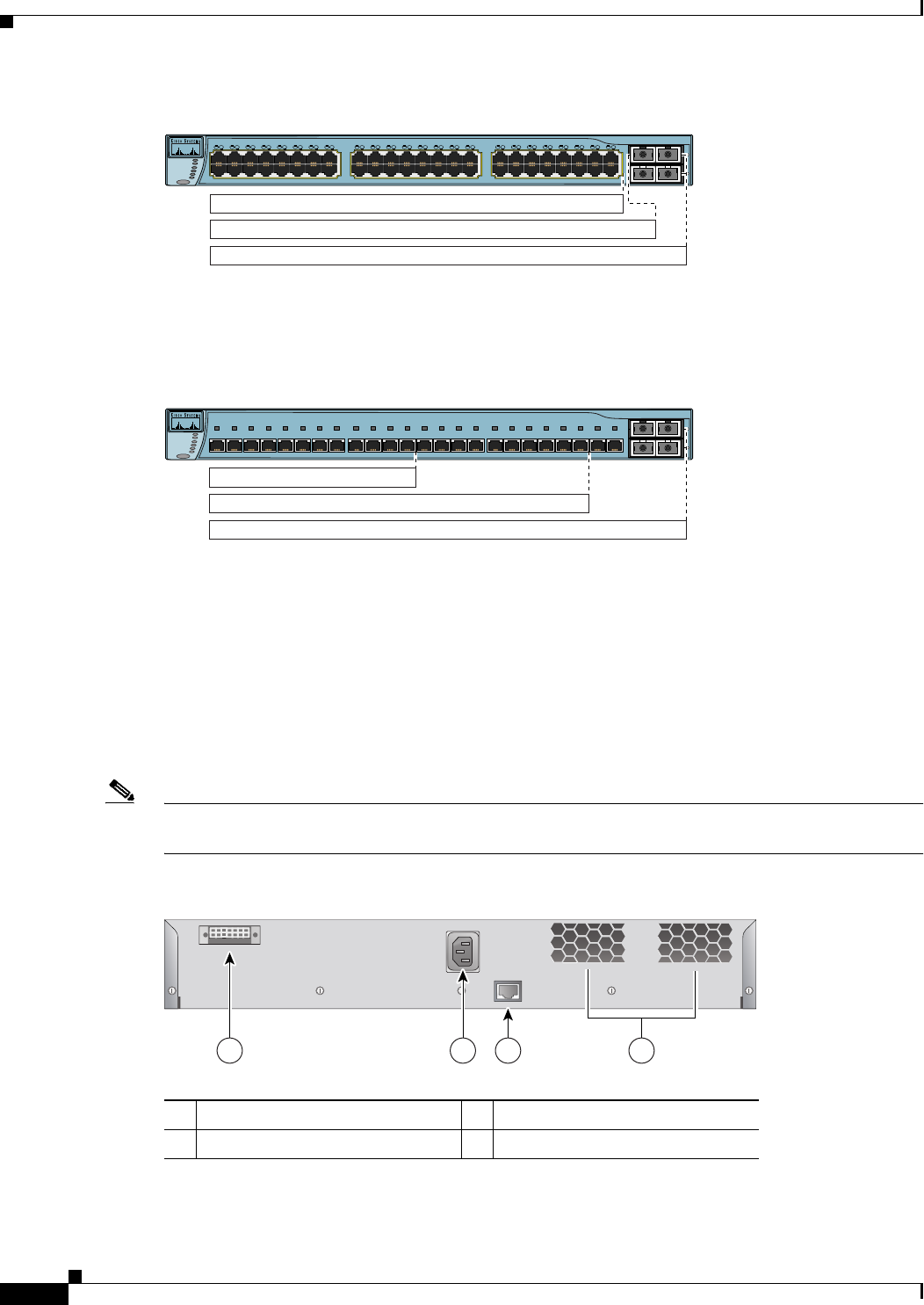
Rear-Panel Description
Other than the Catalyst 3550-24-DC switch, the switch rear panels have an AC power connector, an RPS
connector, and an RJ-45 console port, which are shown in Figure 1-9 and described in this section.
The rear panel of the 3550-24-DC switch has a DC power connector (also referred to as the terminal
block header), an RJ-45 console port, and a ground lug. The switch is shipped with a terminal block plug
in the DC power connector.
Note Figure 1-9 shows the Catalyst 3550-12T switch as an example. All the Catalyst switches have similar
components.
Figure 1-9 Switch Rear Panel
SPEED
SYSTEM
RPS
STATUS
MODE
UTIL
DUPLX
74024
2
1
< 25% +
1
1X
2X
15X
16X
2 3 24 56 78 910 1112 1314 1516 17
17X
18X
31X
32X
18 1920 2122 2324 2526 2728 2931 3132 33
33X
34X
47X
48X
34 3536 3738 3940 4142 4344 4546 4748
50% +
25% – 49% +
Catalyst 3550 SERIES
SPEED
SYSTEM
RPS
STATUS
MODE
UTIL
DUPLX
74099
2
1
< 25% +
50% +
25% – 49% +
Catalyst 3550 SERIES
1 RPS connector 3 Console port
2 AC power connector 4 Fan exhaust
100-240V~
5-3A
50/60Hz
DC OUTPUT 1
CONSOLE
101604
1 2 3
4


