—38—
B. Cleaning and Adjustment
1. Remove burner rack from unit as described in Main
Burner Removal section on page 37.
2. Inspect burners, and if dirty, remove burners from
rack.
3. Using a soft brush, clean burners and crossover port
as required.
4. Adjust spark gap. See Fig. 44.
5. Reinstall burners on rack.
6. Reinstall burner rack as described above.
XI. FILTER DRIER
Replace whenever refrigerant system is exposed to
atmosphere.
XII. PROTECTIVE DEVICES
A. Compressor Protection
Overcurrent
Each compressor has internal line break motor protection.
Crankcase Heater
All units are equipped with a 70-watt crankcase heater to
prevent absorption of liquid refrigerant by oil in the crank-
case when the compressor is idle. The crankcase heater is
energized whenever there is main power to the unit and the
compressor is not energized.
IMPORTANT: After prolonged shutdown or servicing, ener-
gize the crankcase heaters for 24 hours before starting the
compressors.
Compressor Lockout
If any of the safeties (high-pressure, low-pressure, freeze
protection thermostat, compressor internal thermostat) trip,
or if there is loss of power to the compressors, the cooling
lockout (CLO) will lock the compressors off. To reset, manu-
ally move the thermostat setting.
B. Evaporator Fan Motor Protection
A manual reset, calibrated trip, magnetic circuit breaker
protects against overcurrent. Do not bypass connections or
increase the size of the breaker to correct trouble. Determine
the cause and correct it before resetting the breaker.
C. Condenser-Fan Motor Protection
Each condenser-fan motor is internally protected against
overtemperature.
D. High and Low-Pressure Switches
If either switch trips, or if the compressor overtemperature
switch activates, that refrigerant circuit will be automati-
cally locked out by the CLO. To reset, manually move the
thermostat setting.
E. Freeze Protection Thermostat (FPT)
An FPT is located on the top and bottom of the evaporator
coil. They detect frost build-up and turn off the compressor,
allowing the coil to clear. Once the frost has melted, the
compressor can be reenergized by resetting the compressor
lockout.
XIII. RELIEF DEVICES
All units have relief devices to protect against damage from
excessive pressures (i.e., fire). These devices protect the high
and low side.
XIV. CONTROL CIRCUIT, 24-V
This control circuit is protected against overcurrent by a
3.2 amp circuit breaker. Breaker can be reset. If it trips,
determine cause of trouble before resetting. See Fig. 45 and
46 for typical wiring diagrams.
XV. REPLACEMENT PARTS
A complete list of replacement parts may be obtained from
any Bryant distributor upon request.
XVI. DIAGNOSTIC IGC CONTROL LEDs
The unit control boards have LEDs for diagnostic purposes.
Refer to Troubleshooting section on page 43.
XVII. OPTIONAL HINGED ACCESS DOORS
When the optional hinged access doors option is ordered, the
unit will be provided with external and internal hinged
access doors to facilitate service.
Four external hinged access doors are provided on size 180-
240 units. Two external hinged doors are provided on size
300 units. All external doors are provided with 2 large
1
/
4
turn latches with folding bail-type handles. (Compressor
access doors have one latch.) A single door is provided for
filter and drive access. One door is provided for control box
access. The control box access door is interlocked with the
non-fused disconnect which must be in the OFF position to
open the door. Two doors are provided on 580F180-240 units
for access to the compressor compartment.
Two internal access doors are provided inside the filter/drive
access door. The filter access door (on the left) is secured by
2 small
1
/
4
turn latches with folding bail-type handles. This
door must be opened prior to opening the drive access door.
The drive access door is shipped with 2 sheet metal screws
holding the door closed. Upon initial opening of the door,
these screws may be removed and discarded. The door is
then held shut by the filter access door, which closes over it.
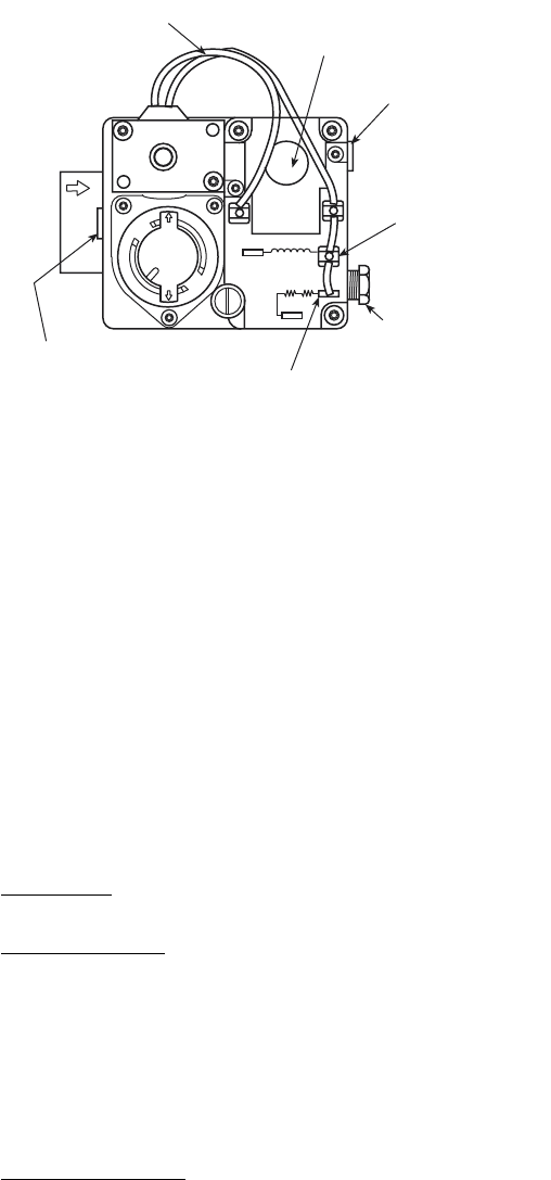
OFF
ON
W-1
W-2
D-1
D-2
C1
C2
PILOT
ADJ.
INLET PRESSURE TAP
(PLUGGED)
1/8 - 27 N.P.T. THDS.
2 LEADS, #18 WIRE 1/32 INSULATION,
600V. MAX., 105
°
C
REGULATOR
ADJUSTMENT SCREW
(REMOVE COVER)
OUTLET PRESSURE
TAP (PLUGGED)
1/8-27 N.P.T. THDS.
PILOT CONNECTION
FOR 1/4” O.D. TUBING
(PLUGGED)
RECEPTACLE AND
TAB COMBINATION
TERMINAL
RECEPTACLE TERMINAL
Fig. 43 — Gas Valve


