Page 33
SYSTEMS DESCRIPTIONS
Computer Calibration Instructions for Controller
Introduction: The following procedure is for cali-
bration of the RA500 Series Controller. Calibrate
the controller only if ramp does not function
properly.
Electronic Controller can be calibrated using a
computer (recommended) or manually using the
onboard Calibrate button and potentiometers.
Computer Calibration procedures are provided for
Microsoft Windows XP. Other Operating Systems
may vary. Consult the operating system search
menu or users guide for alternate routes and proce-
dures to access port settings.
Electronic Controller
Connect the Computer to the Controller:
1. Remove the controller cover. Press the “Cali-
brate” button and then the “Calibrate Reset”
button to restore factory defaults (see Figure S).
2. Locate J9 (9-pin Port) and connect a serial
cable from J9 to an available COM slot on the
computer.
Establish a connection between the computer
and the controller:
Note: This is done from the computer after the
physical connection has been made.
1. In the start menu, go to “Programs” and select
“Accessories.”
2. Under “Accessories”, choose “Communica-
tions”, and then “Hyperterminal.” Once select-
ed, a “Connection Description” window will pop
up.
3 Under name: Enter “RA500” and hit OK. A
“Connect To” window will then pop up.
4. Under the “Connect Using” line, select the com
port that the serial cable is connected to (typi-
cally COM1) and hit OK.
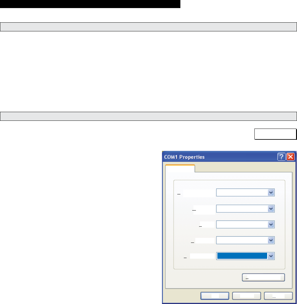
5. A window similar to the one in Figure R will
pop up. Ensure the settings match the settings
listed in Figure R. Press OK.
Bits per second:
Port Settings
Data bits:
Parity:
Stop bits:
Flow control:
8
None
None
1
19200
Restore Defaults
OK Cancel
Apply
Figure R
