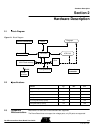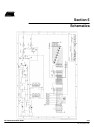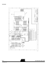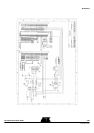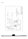
Hardware Description
C51 Microcontrollers Demo Board User Guide 2-6
4119C–8051–3/03
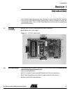
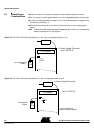
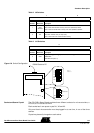
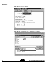
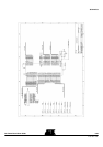
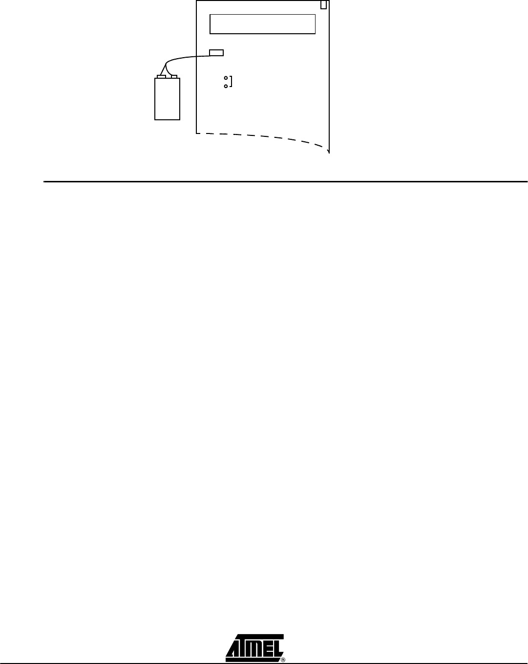
Figure 2-4. C51/C251 Demo Board Powered by J2.
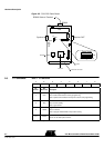
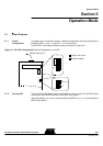
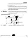
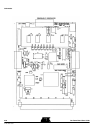
2.5 Board Layout n On-Off
– Switches ON the power supply.
n
Reset
– Resets the microcontrollers.
n
INT1#
– Issues an interruption on microcontollers on INT1# pin.
n
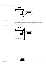
J8 Connector
– Configure hardware in Page Mode or Non Page Mode.
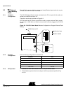
– for C251 microcontrollers. For C51 products, the configuration must be set to
Non Page Mode.
n
Synchro IN
– Used to connect several C51/C251 Demo Boards together, provides global
reset / interrupt for all connected C51/C251 Demo Boards.
n
Synchro OUT
– Only one power supply is needed but it may be able to deliver enough
current to supply all the C51/C251 Demo Boards.
– There are no rules to connect two boards together anyone of the two DB9
may be used.
n
RS232
– Used to connect a terminal or through an RS232 serial communication port.
– This serial port can be used for displaying messages or for programming
external Flash memory.
Note: The cable that connect this RS232 Connector MUST be a pin to pin cable.
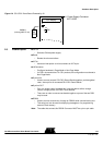
J18
ON
J1 Power Supply Connector
9V
PP3
J2
battery
NOT USED
(rechargeable or not)
LCD display