12
AVR430
8124C-AVR-10/08
4.5 Upgrading the MC300
As the board is shipped, its limitations are Vm
max
=40V and Im
max
=6A. These limits can
be increased by replacing the relevant components (not included).
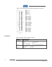
4.5.1 Voltage limitations
If a Vm
max
higher than 40V is required, then some components must be changed on
the board. Components limiting Vm, listed with lowest voltage ratings first, are shown
in Table 4-1.
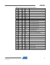
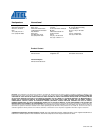
Table 4-1. Components influenced by Vm.
Component designator(s) Component name Limiting parameter
Q3, Q4, Q5, Q6, Q7, Q8, Q9 & Q10 IRFR3504 V
DSS
= 40V
C10, C19, C26 & C33 100nF V
max
= 50V
Q2 2N7002 V
DSmax
= 60V
C14 47uF/63V V
max
= 63V
D8, D12, D13 & D14 BAS16 V
RRM
= 85V
D9 10MQ100N V
RRM
= 100V
D11 12CWQ10FN V
RRM
= 100V
C7 10nF V
max
= 100V [2]
R7 100kOhm Pmax = 0.1W -> Vm = 108V
The integrated bridge drivers (IR2101S) can handle up to 600V, but the layout of the
PCB (spacing between tracks) should be considered before operation at high
voltages.
If filters/dividers for Vm, U, V, W, or X have been mounted, verify that they can handle
Vm.
4.5.2 Current limitations
For an Im > 5A, use power connector J3 and not DC-Jack J5. If an Im
max
larger than
6A is required, components listed in Table 4-2 are affected.
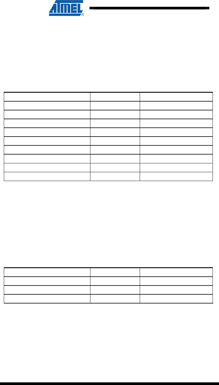
Table 4-2. Components conducting Im.
Component designator(s) Component name Limiting parameter
R62 50mOhm 2W I
max
= sqrt(P/R) = 6,0A
(1)
J3 & J7 MC1,5/x-G-3,81 I
max
= 8A
Q3, Q4, Q5, Q6, Q7, Q8, Q9 & Q10 IRFR3504 I
D
= 30A
Notes: 1. The pad/track area around R62 is not 300mm2 as required by datasheet for
handling 2W. Reducing P to 1,8W gives I
max
= sqrt(P/R) = 6,0A.
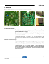
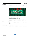
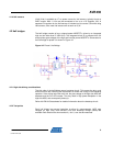
4.5.3 Additional decoupling capacitors on Vm
The board has provision for some extra decoupling capacitors on Vm. They are found
close to the MOS bridges (C11, C12, C20, C21, C27, C28, C34 and C35), and one
close to the power input (C13).