3
Note: the detachable 4-pin section cannot be used
in place of a 4-pin +12V connector.
3. Connect the Reset switch (labeled RESET SW) to
the motherboard at the RST connector. Polarity
(positive and negative) does not matter for switches.
4. Power Switch (labeled POWER SW) connects to the
PWR connector on the motherboard.
5. Power LED (labeled POWER LED) connector is located behind the Reset
connector. For LEDs, colored wires are positive (+). White or black wires are
negative (–). If the LED does not light up when the system is powered on,
try reversing the connection. For more info on connecting LEDs to your
motherboard, see your motherboard manual.
6. Hard Drive LED (labeled HDD LED) connects to the IDE connector.
USB Connection
You will find a single 10-pin connector on a cable attached to the front USB ports.
This is an Intel standard connector, which is keyed so that it can’t be accidentally
reversed as long as it is connected to a proper Intel standard motherboard header.
Connect the 10-pin connector to the motherboard headers so that the blocked pin
fits over the missing header pin.
Note: Please check the motherboard manual for the USB header pin layout and
make sure it matches the table below. If it does not match this Intel® standard,
please visit Antec’s web store at http://www.antec.com/StoreFront.bok and
search for part number 30095 to order a USB Internal Adapter Cable. This adapter
will allow you to connect the front USB to your motherboard on a pin-by-pin basis.
Motherboard Pin Layout
Connecting the IEEE 1394 (FireWire®, i.Link®) Port
You will find a single 10-pin connector on a cable attached to the front IEEE 1394
connection. This is an Intel standard connector, which is keyed so that it can’t be
accidentally reversed as long as it is connected to a proper Intel standard moth-
erboard header. Connect the 10-pin connector to the motherboard header so that
the blocked pin fits over the missing header pin.
Note: Please check the motherboard manual for your IEEE 1394 header pin layout
and make sure it matches the table below. If you intend to connect the front
FireWire port to an IEEE 1394 add-on card that comes with an external-type IEEE
1394 connector, you will need a FireWire Internal Adapter. To order one, please
visit Antec’s web store at http://www.antec.com/StoreFront.bok and search for
part number 30031. This adapter will allow you to connect the front IEEE 1394
port to the external-type connector.
Pin Signal Names Pin Signal Names
1
USB Power 1
2
USB Power 2
3
Negative Signal 1
4
Negative Signal 2
5
Positive Signal 1
6
Positive Signal 2
7
Ground 1
8
Ground 2
9
Key (No Connection)
10
Empty Pin
12
109
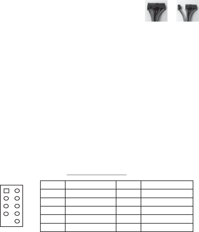
Picture 2 Picture 3
For 24-pin
motherboards
For 20-pin
motherboards


