POEFEM24T2SFP User Manual
6
Alloy Computer Products Pty Ltd Copyright ©2006
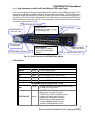
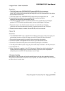
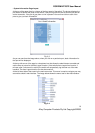
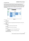
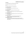
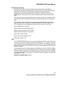
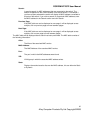
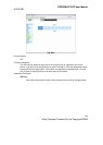
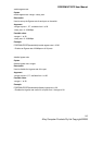
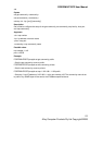
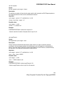
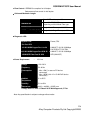
1.4.1. User Interfaces on the Front Panel (Button, LED's and Plugs)
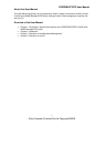
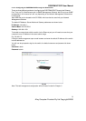
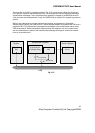
There are 24x copper RJ-45 Fast Ethernet ports and 2x paired 10/100/1000Mbps Copper / SFP
fibre ports for optional mini-GBIC modules on the front panel of the switch. The LED display area,
located on the left side of the panel, contains a Power LED (which indicates the power status of
the switch) a CPU LED (which indicates whether the CPU is working correctly) and 26 LED's that
indicate the status of each of the RJ-45 ports on the switch. There are also 2 LED’s that indicate
the status of each of the SFP ports.
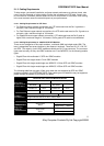
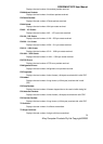
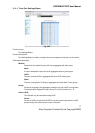
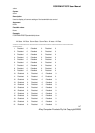
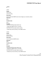
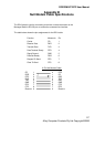
LED Indicators
LED Colour Function
System LED
POWER
Green Lit when power is active
CPU
Green Blinks when CPU is active
ACT
Green Lit when LEDSET set on active mode
FDX
Green Lit when LEDSET set on full-duplex mode
SPD
Green Lit when LEDSET set on speed mode
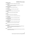
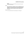
10/100Mbps Ethernet Copper Ports 1 to 24
LINK
Green
- On when connection with remote device is good
- Off when no link is present
ACT/FDX/ SPD
Amber
- LEDSET set on ACT (active) mode:
Blinks when any traffic is present
- LEDSET set on FDX (full-duplex) mode:
Lit when full-duplex mode is active
Blinks when any collision is present
- LEDSET set on SPD (speed) mode:
Lit when 100Mbps speed is active
Off when 10Mbps speed is active
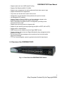
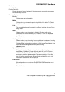
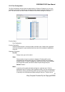
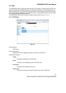
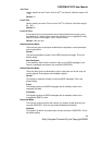
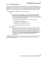
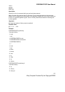
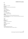
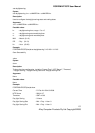
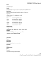
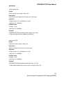
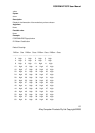
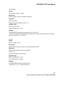
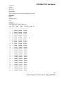
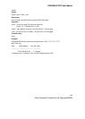
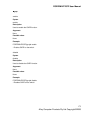
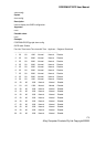
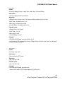
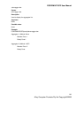
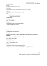
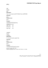
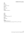
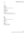
Fi
. 1-2 : Front
iew of the POEFEM24T2SFP Switch
Power Indication
LED & CPU LED
Fast Ethernet Ports
RESET Button:
RESET button is used to
restore the system default
settings.
LED SET Mode: ACT/FDX/SPD
LEDSET Button:
LEDSET button is used to change
the LED display mode
PoE Port Status
Indication LEDs
TP Port Status Indication LEDs
Fibre Port Status Indication LEDs
Gigabit Dual Media
Port(25~26): SFP/TP