Introduction to Programming The Status Model
38 Agilent 8163A/B, 8164A/B & 8166A/B Mainframes, Fifth Edition
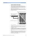
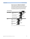
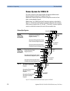
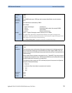
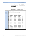
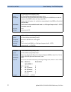
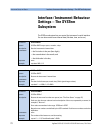
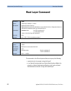
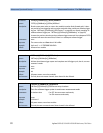
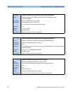
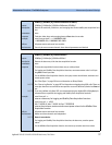
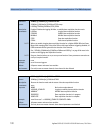
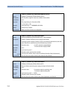
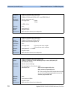
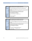
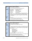
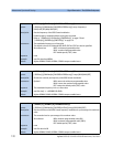
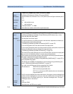
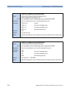
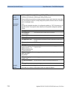
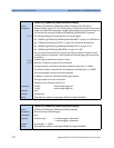
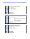
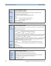
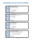
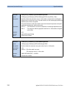
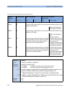
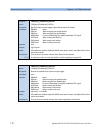
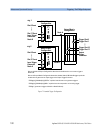
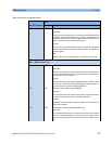
Operation/Questionable Status Summary Register
• Bits 0 to 4 are built from the OSSER/QSSER and the OSSEM/QSSEM.
• A summary of the event register, the condition register and the enable
mask is set in the status byte.
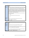
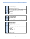
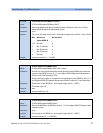
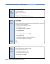
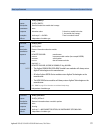
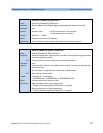
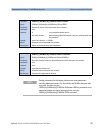
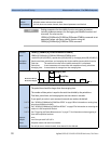
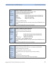
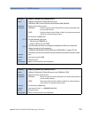
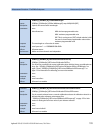
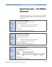
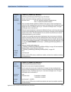
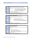
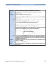
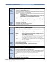
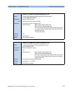
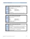
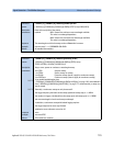
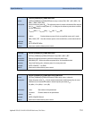
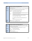
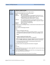
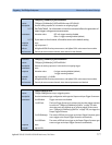
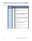
Operation/Questionable Slot Status
• The Operation/Questionable Slot Status consist of a condition and an
event register.
• A "rising" bit in the condition register is copied to the event register.
• A "falling" bit in the condition register has no effect on the event
register.
• Reading the condition register is non-destructive.
• Reading the event register is destructive.
• A summary of the event register, the condition register and the enable
mask is set in the status byte.
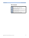
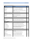
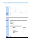
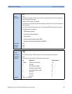
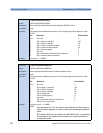
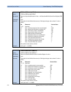
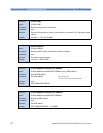
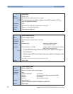
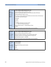
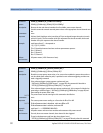
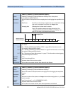
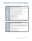
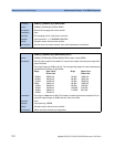
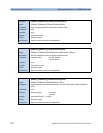
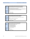
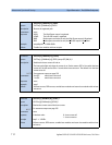
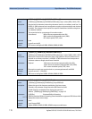
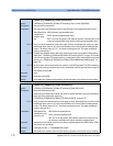
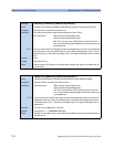
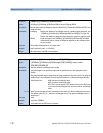
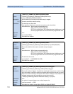
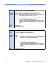
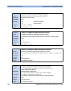
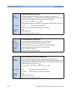
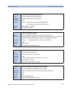
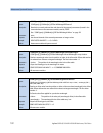
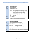
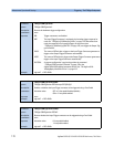
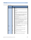
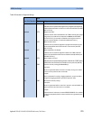
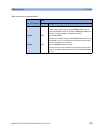
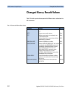
Operation Slot Status Register
• Bit 0 is set if the laser is switched on.
• Bit 1 is set if the Coherence Control is switched on.
• Bit 3 is set if Power Meter zeroing or Tunable Laser module lambda
zeroing is ongoing.
• Bit 4 is set if the attenuator output is enabled (shutter open).
• Bits 5 - 7 are set if the wavelength offset table is enabled (see page 68).
• All other bits are unused, and therefore set to 0.
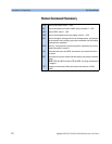
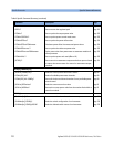
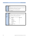
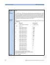
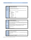
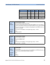
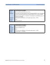
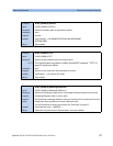
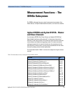
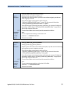
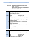
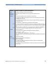
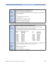
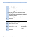
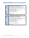
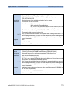
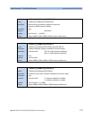
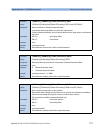
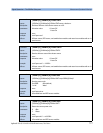
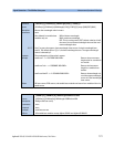
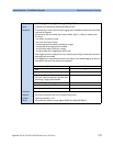
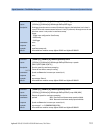
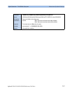
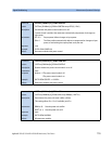
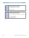
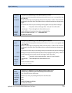
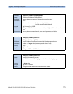
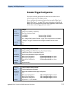
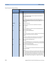
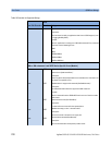
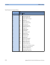
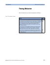
Questionable Slot Status Register
• Bit 0 is set if excessive power is set by the user for any source module
or if excessive averaging time is set for any Power Meter.
• Bit 1 is set if the last Power Meter zeroing failed.
• Bit 2 is set if temperature is out of range.
• Bit 3 is set if laser protection is switched on.