2-10 Installing the PathBuilder S21x Switch Hardware
Front Panel Dip Switches
Front Panel Dip Switches
Introduction
This section describes the front panel dip switches on the PathBuilder S21x switch.
Front Panel
Switches
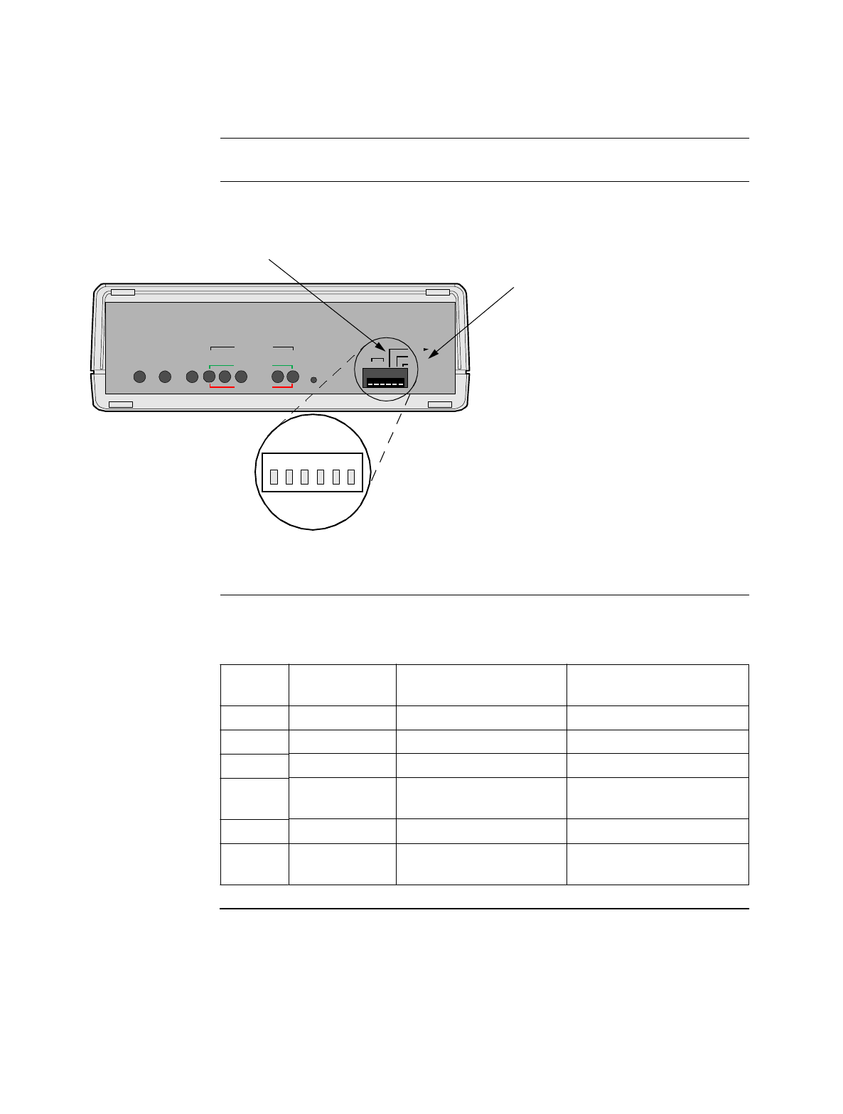
Figure 2-4 illustrates the switches found behind the front panel of the PathBuilder
S21x switch.
Figure 2-4. PathBuilder S21x Switch Front Panel Switches
Front Panel DIP
Switch Setting
The six DIP switches on the front panel are defined as follows:
POWER
DATA IN
CTP-- PORT 4
DIAG.
DFLT NODE
3 3
TM
RI
Port
MB
RESET
STATUS
TEST
WATCHDOG
LAN 4 3 2 1
Default Node
To reset all configurable parameters, put
switch in up position and Power Cycle (or
Reset), then put switch in down position
and Power Cycle (or Restart) again.
Control Port Switch
Defaults Port 3 to 9600 bps 8N1.
1234
56
DATA OUT
PORT
Switch
Posn.
Switch
Name
Down Up
1 RI/TM Pin 22 - Ring Indicator DCE Test Mode Input
2 MB/TM Pin 22 - Make Busy DTE Test Mode Input
3 N/A N/A N/A
4 CTP-Port 4 Normal operation Configure Port 4 as PAD
port
5 DIAG Normal operation Execute diagnostics
6 DFLT-NODE Normal operation Reset CMEM
configuration


