


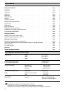
INSTALLATION
4
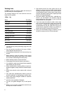
Unpacking
Before starting the machine up, the packing must be
removed as follows.
You are advised to keep all the packaging for re-use in
case the machine is to be transported again.
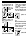
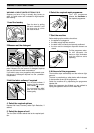
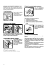
Using a spanner unscrew
and remove the rear right
bolt. Lay the machine
gently on its back, making
sure that the hoses are
not squashed.
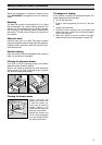
Remove the polystyrene block from the bottom of the
machine.
Carefully slide out the right polythene bag (1), removing
it toward the centre of the machine.
Repeat the operation for the left polythene bag (2),
removing it toward the centre of the machine.
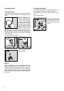
Remove the polystyrene
base, set the machine
upright and unscrew the
two remaining rear bolts.
Slide out the 3 plastic spacers and plug the 3 holes with
the 3 plastic plugs which you can find at the back of the
machine.
Positioning
Your new washing machine has been designed to be
permanently plumbed in to your home’s water supply
and drainage system. However, if this is not possible, it
may be connected to suitable existing taps with the drain
hose discharging into a sink.
The appliance has two inlet hoses, hot and cold, with
female 3/4” BSP thread connectors. If this connection is
not compatible with the plumbing of the existing installa-
tion, a variety of connectors are available from good
hardware stores and plumbers merchants to suit most
domestic plumbing. Any alteration to your existing plum-
bing must be carried out by a competent person, or qua-
lified plumber.
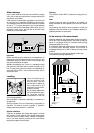
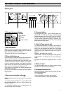
Water inlet
The inlets on the back of the appliance are colour coded,
blue for cold and red for hot.
Before connecting the
hoses be sure to fit the
mesh filters supplied as
per diagram.
If only a cold water supply is available, connect the two
hoses to a cold water outlet by means of a «Y» connec-
tion piece.
Installation should comply with local water authority and
building regulations’ requirements.
The appliance must be given a separate cold water sup-
ply and not be connected to a mixer tap, a single outlet
water heater or a booster pump. A minimum water pres-
sure of 7 psi is required for safe operation of the appli-
ance.
If you cannot make the cold water connection direct from
the rising mains, you may be able to operate the appli-
ance from your cold water storage system.
There should be a minimum distance of 5.02m (16
1
/
2
ft)
between the appliance’s inlet and the bottom of the tank.
There will be sufficient pressure for the hot water supply
from the hot water cylinder if the height between the
appliance’s inlet and the bottom of the cold water stor-
age cistern (not between the appliance and hot water
cylinder) is at least 2.74m (9ft).
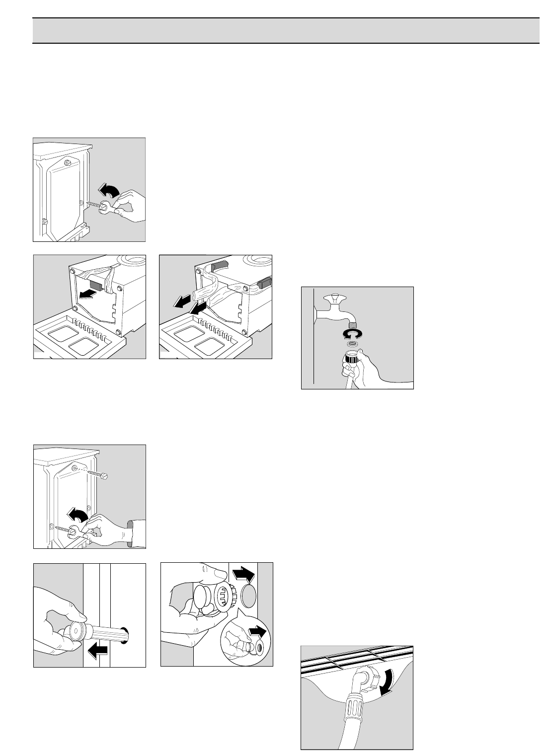
Set the hoses correctly by
loosening the ring nuts.
After positioning the inlet
hoses, be sure to tighten
the ring nuts again to pre-
vent leaks.
P0255
P0234
P0233
2
1
P0256
P0001
P0002
P0003
P0021