


10
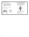
■ Installed in a confined area:
If the dryer is installed in a confined area such as a
bathroom or closet, provision must be made for enough
a
ir for combustion and ventilation. Check governing
codes and ordinances or refer to the “Recessed Area
and Closet Installation Instructions” in the Location
R
equirements section.
Gas Supply Pressure Testing
A
1
⁄8" NPT minimum plugged tapping, accessible for gauge
t
esting, must be installed immediately upstream of the installed
shut-off valve to the dryer.
The dryer must be disconnected from the gas supply piping
system during any pressure testing of the system at test
pressures in excess of
1
⁄2" psig.
Venting Requirements
WARNING: To reduce the risk of fire, this dryer MUST BE
EXHAUSTED OUTDOORS.
■ The dryer vent must not be exhausted into any gas vent,
chimney, wall, ceiling, attic, crawlspace, or a concealed space
of a building.
■ Only rigid or flexible metal duct shall be used for exhausting.
■ Do not use an exhaust hood with a magnetic latch.
■ Do not install flexible metal vent in enclosed walls, ceilings,
or floors.
■ 4" (102 mm) heavy metal vent and clamps must be used. Do
not use plastic or metal foil vent.
■ Use clamps to seal all joints. The duct shall not be assembled
with screws or other fastening means that extend into the
duct and catch lint. Do not use duct tape.
■ The total length of flexible metal vent shall not exceed 8 ft
(2.4 m).
IMPORTANT: Observe all governing codes and ordinances.
Rigid metal vent is recommended to prevent crushing and
kinking.
Flexible metal vent must be fully extended and supported when
the dryer is in its final position. Remove excess flexible metal vent
to avoid sagging and kinking that may result in reduced airflow
and poor performance.
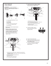
An exhaust hood should cap the vent to prevent rodents and
insects from entering the home or business.
Exhaust hood must be at least 12" (30.5 cm) from the ground
or any object that may be in the path of the exhaust (such as
flowers, rocks, or bushes).
If using an existing vent system, clean lint from the entire length
of the system and make sure exhaust hood is not plugged with
lint. Replace any plastic or metal foil vent with rigid metal or
flexible metal vent.
P
lan installation to use the fewest number of elbows and turns.
Allow as much room as possible when using elbows or making
turns. Bend vent gradually to avoid kinking.
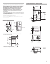
Vent outlet is located at the back of the dryer, at bottom center.
The vent can be routed up, down, left, right, behind the dryer,
or straight out the back of the dryer.
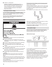
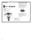
Vent System Length
Maximum length of vent system depends upon the type of
vent used, number of elbows, and type of exhaust hood. The
maximum length for rigid vent is shown in the chart.
For vent systems not covered by the vent specification chart,
see your parts distributor.
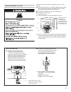
If dryer is installed in a confined area, such as a bedroom,
bathroom, or closet, provision must be made for enough air
for combustion and ventilation. (Check governing codes and
ordinances.) See “Recessed Area and Closet Installation
Instructions” in the Location Requirements section.
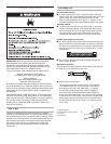
A 4" (10.2 cm) outlet hood is preferred. However, a 2
1
⁄2" (6.4 cm)
outlet exhaust hood may be used. A 2
1
⁄2" (6.4 cm) outlet creates
greater back pressure than other hood types. For permanent
installation, a stationary vent system is required.
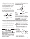
A
B
Exhaust Air Flow
A. Good
B. Better
Rigid Metal Vent
No. of 90° turns
4" (10.2 cm) Diameter Exhaust Hoods
Maximum Vent Length
0
1
2
3
4
Box Hood and Louvered Style Angled Hood Style
130 ft. (39.6 m)
125 ft. (38.1 m)
115 ft. (35.1 m)
106 ft. (32.3 m)
98 ft. (29.9 m)
129 ft. (39.3 m)
119 ft. (36.3 m)
109 ft. (33.2 m)
100 ft. (30.5 m)
92 ft. (28.0 m)