


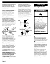
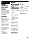
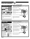

MAXIMUM LENGTH OF 4-INCH (10.2 cm) DIAMETER
RIGID METAL VENT
No.
of 90°
turns
EXHAUST HOOD TYPE
2-1/2"
(6.4 cm)
4"
(10.2 cm)
4"
(10.2 cm)
4"
(10.2 cm)
4"
(10.2 cm)
4"
(10.2 cm)
64 FT. (19.5 m)
54 FT. (16.5 m)
44 FT. (13.4 m)
35 FT. (10.7 m)
27 FT. (8.2 m)
64 FT. (19.5 m)
54 FT. (16.5 m)
44 FT. (13.4 m)
35 FT. (10.7 m)
27 FT. (8.2 m)
0
1
2
3
4
58 FT. (17.7 m)
48 FT. (14.6 m)
38 FT. (11.6 m)
29 FT. (8.8 m)
21 FT. (6.4 m)
MAXIMUM LENGTH OF 4-INCH (10.2 cm) DIAMETER
FLEXIBLE METAL VENT
36 FT. (11.0 m)
31 FT. (9.4 m)
27 FT. (8.2 m)
25 FT. (7.6 m)
23 FT. (7.0 m)
36 FT. (11.0 m)
31 FT. (9.4 m)
27 FT. (8.2 m)
25 FT. (7.6 m)
23 FT. (7.0 m)
0
1
2
3
4
28 FT. (8.5 m)
23 FT. (7.0 m)
19 FT. (5.8 m)
17 FT. (5.2 m)
15 FT. (4.6 m)
The console houses the accumulator
timer with actuating arm and button.
The timer is set to provide 45 minutes
(4 pins) of drying time when activated
by the coin slide. Timer cams for
30- minute (6 pins) and 60-minute
(3 pins) drying times are included in
the parts bag.
The coin-slide mechanism, control
panel lock and key, and coin-box lock
and key are not included and are
available from usual industry sources.
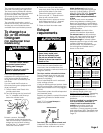
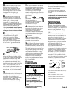
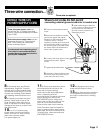
3. Insert a narrow, flat-blade
screwdriver under the timing cam
near the clock shaft. Gently lift cam
straight up and off shaft making
sure that the “V” -shaped notch
clears the ratchet tooth.
Each coin-operated dryer is
equipped with a 45-minute timer
cam that provides 45 minutes of
drying time when activated by the
coin slide.
You can install the 30-minute or
60-minute timing cam (shipped with
dryer) as follows:
1. Unlock meter case. Reach into
control panel area.
2. Turn the timing cam by hand until
the “V” -shaped notch lines up
below the ratchet tooth.
Line up
notch to
clear
ratchet
tooth.
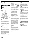
hub
down
timing cam
drive
lug
To change to a
30- or 60-minute
timingcam
(for mechanical timer
models only)
ratchet tooth
Disconnect power before
making cam changes.
Failure to do so can result in
death or electrical shock.
Electrical Shock Hazard
WARNING
4. Place new cam (hub side down)
over clock shaft. Line up flat side of
shaft with flat side of cam hole.
Check that drive lug is in place.
5. Turn cam until “V” -shaped notch
lines up with ratchet tooth.
6. Press cam down in place on motor
shaft. Make sure that “V” -shaped
notch clears the ratchet tooth.
7. Close and lock the meter case.
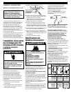
Exhaust
requirements
Do not use non-metal flexible vent,
metal vent that is smaller than four
inches in diameter or exhaust hoods with
magnetic latches.
The dryer must be exhausted outdoors.
Do not exhaust dryer into a gas vent,
chimney, wall, ceiling, or concealed
space of a building.
Do not install flexible vent in enclosed
walls, ceilings or floors.
If using an existing exhaust system, clean
lint from entire length of exhaust system.
Make sure exhaust hood is not plugged
with lint.
The exhaust system should be inspected
and cleaned yearly.
Replace any plastic or metal foil exhaust
vent with rigid metal or flexible metal
vent.
Fire Hazard
Use a heavy metal vent.
Do not use a plastic vent.
Do not use a metal foil vent.
Failure to do so can result in
death or fire.
WARNING
Metal flexible vent must be fully
extended and supported when the
dryer is in its final position. DO NOT
KINK OR CRUSH THE VENT. The metal
flexible vent must be completely
open to allow adequate exhaust air
to flow.
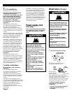
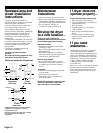
Allow as much room as possible
when using elbows or making turns.
Bend vent gradually to avoid kinking.
Remove excess flexible vent to avoid
sagging and kinking that may result in
reduced air flow.
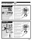
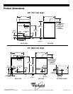
Exhaust outlet is located at the
center of the bottom dryer back.
The exhaust vent can be routed up,
down, left, right, behind the dryer or
straight out the back of the dryer.
Maximum length of exhaust system
depends upon the type of vent used,
number of elbows and type of
exhaust hood. The maximum length
for both rigid and flexible vent is
shown in the chart.
Four-inch (10.2 cm) metal exhaust vent
is required. Plan installation to use the
fewest number of elbows and turns.
Use 4" (10.2 cm) vent clamps to
secure vent system.
better
exhaust
airflow
exhaust airflow
good
exhaust
airflow
For exhaust systems not covered by
the exhaust length chart, see
Whirlpool Service Manual
, “Exhausting
Whirlpool Dryers,” Part No. 603197,
available from your Whirlpool parts
distributor.
If dryer is installed in a confined area,
such as a bedroom, bathroom or
closet, it must be exhausted to the
outside and provision made for
enough air for combustion and
ventilation. (Check governing codes
and ordinances.) See “Recessed area
and closet installation instructions” on
Page 12.
Page 3