


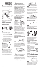
Panel D
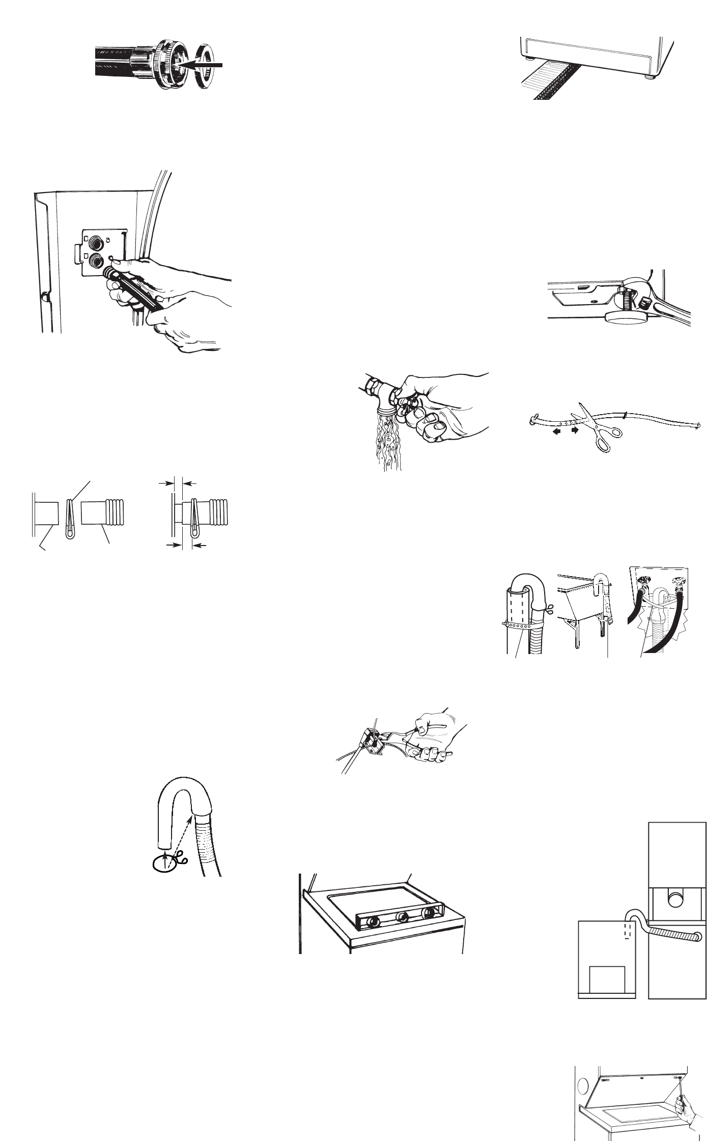
Inlet valves are
plastic. Do not
strip or
crossthread.
6.Attach hose to bottom inlet valve
opening first; then second hose to top
inlet valve. Tighten couplings by hand.
Then use pliers to make an additional
two-thirds turn.
IMPORTANT: THIS PROCEDURE
MUST BE FOLLOWED TO ASSURE
PROPER INSTALLATION.
8.Standpipe or
laundry tub drain system:
Open clamp and slide
over “hook” end of drain
hose to secure the rigid
and corrugated
sections together.
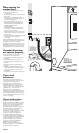
7.To prevent the drain hose from
coming off or leaking, it must be
installed per the following instructions:
1. Wet the inside end of the drain
hose with tap water. DO NOT USE
ANY OTHER LUBRICANT.
2. Squeeze ears of clamp with pliers
to open and place clamp over the
end of the drain hose.
3. While holding clamp open, work
end of drain hose onto drain
connector.
4. Position clamp over the drain hose
area marked “clamp.” Release
clamp. Clamp should be 1/4 inch
from end of drain hose.
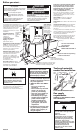
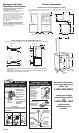
9.In a 24-inch-wide area that will be
behind the washer/dryer, securely
mount the 24-inch-long, 1-inch x 4-inch
board across two wall studs or on a
concrete wall so that it is 28 inches
minimum above the floor and no more
than 41 inches above the floor. Attach
the cable bracket to the 1-inch x 4-inch
board with four screws. (See Panel F.)
10.Slide washer/dryer onto
cardboard or hardboard before moving
across floor. If you have room to work
from either side of the washer/dryer,
move washer/dryer close to final
position so you can easily complete the
following steps. (Go to Step 11.)
If you are working in a closet or
recessed area, move the washer/dryer
into its final position and remove
cardboard or hardboard from under
washer/dryer. Remove the access
panel by removing three Phillips-head
screws and one bumper, located at the
top of the access panel. Set panel,
screws and bumper aside. (See Step
19.) Complete the following steps
through the access area.
11.Put “hook” end of drain hose
into laundry tub or standpipe. Check for
proper length of drain hose.
DO NOT FORCE EXCESS LENGTH OF
DRAIN HOSE DOWN THE STANDPIPE. THIS
COULD CAUSE SIPHONING.
12.Before
attaching water
inlet hoses, run
water through both
faucets into a
bucket. This will get
rid of particles in
water lines that might
clog hoses. Mark
which is the hot water faucet.
Replace inlet hoses after 5 years of use
to reduce the risk of hose failure. Inspect
and replace inlet hoses if bulges, kinks,
cuts, wear, or leaks are found. When
replacing your inlet hoses, mark the
date of replacement on the label with a
permanent marker.
13.Attach bottom hose (inlet
marked “H”) to hot water faucet.
Attach top hose (inlet marked “C”) to
cold water faucet. Tighten the coupling
to the faucet by hand. Use pliers to
make final two-thirds turn.
Move washer/dryer to its permanent
location. Remove cardboard from under
washer/dryer.
14.Cut the plastic strap securing
the cable wire bracket to the power
supply cord and discard. DO NOT CUT
CABLE. Remove the power supply cord
from the bracket. Attach the cable wire
bracket to the wall. Check that bracket
is secure. (See Panel F.)
15.Tilt washer/dryer forward raising
back legs 1 inch off of floor to adjust
rear, self-leveling legs. Gently lower
washer/dryer to floor. Check levelness
of the washer/dryer by placing a
carpenter’s level on top of the washer,
first side to side; then front to back. If
washer/dryer not level, check that rear
leveling legs move up and down freely.
If washer/dryer is level, go to Step 17.
Insert corner posts 6 inches
from left leg. Do Not insert
corner posts in the center of
the washer/dryer.
16.If it is not level, carefully tilt
washer/dryer backward until front of
washer/dryer is 3-4 inches off of floor.
Insert 4 corner posts under washer/dryer
about 6 inches from the left leg. Loosen
nuts on each front leg. Adjust the front
legs up or down. Tilt washer/dryer
backward and remove corner posts.
Gently lower the washer/dryer to the
floor. Repeat Step 15. If it is still not level,
repeat Step 16 and then Step 15 until
washer/dryer is level.
17.When washer/dryer is level, use
wrench to turn nuts on front legs up
tightly against washer/dryer base. If nuts
are not tight against washer/dryer base,
the washer/dryer may vibrate.
18.Measure and mark a point
approximately 16 inches from the plug
end of the shipping strap. Cut the
shipping strap at this point.
Check that hose is not twisted or
kinked and is securely in place.
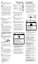
A
B
C
strap strap
Put “hook” end of drain hose in tub or
standpipe. Tightly wrap the shipping
strap around the drain hose and tub or
standpipe or inlet hose as shown in
Figures A-C. Push plug into the nearest
hole in the shipping strap.
Hose must be cut exactly to length so
“hook” end is held tightly over edge of
standpipe.
If drain hose cannot be strapped in
place, it must be cut exactly to length
so the “hook” end is held tightly over the
edge of the tub or
standpipe.
If a longer drain hose is
needed, drain hose (Part No.
388423) and hose extension
kit (Part No. 285442) are
available from authorized
parts distributors. If drain
hose must be
shortened, use
hose kit (Part
No. 285442).
Note: If
washer/dryer
is moved to
adjust drain
hose, the washer/dryer must be leveled
again. Repeat Steps 15-17. Place
cardboard under the washer/dryer and
carefully move washer/dryer to avoid
damaging floor covering.
strap
19.If you did not remove the
access panel in Step 10, remove three
Phillips-head screws and one bumper,
located at the top of the access panel.
Set the panel, screws and bumper
aside.
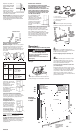
Figure D
16"
16"
drain hose
connector
clamp
drain hose
1/4"
1/4"
max.
16"
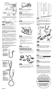
5.Insert a flat washer into each end
of the inlet hoses. Check that washers
are firmly seated in couplings.
washer
coupling