


Exceeding the length of duct pipe or number
of elbows allowed in the "MAXIMUM LENGTH" charts can
cause an accumulation of lint in the exhaust system. Plugging
the system could create a fire hazard, aswell as increase drying
times.
Do not screen the exhaust ends of the vent
system, nor use any screws, rivets or other fastening means
that extend into the duct and catch lint to assemble the
exhaust system. Lint can become caught in the screen, on the
screws or rivets, clogging the duct work and creating a fire hazard
as well as increasing drying times. Use an approved vent hood
to terminate the duct outdoors, and sealall joints with duct tape.
All male duct pipe fittings MUST be installed downstream with
the flow of air.
Explosion hazard. Do not install the dryer
where gasoline or other flammables are kept or stored. If
the dryer is installed in a garage, it must be a minimum of 18
inches (45.7 cm) above the floor. Failure to do so can result in
death, explosion, fire or burns.
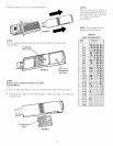
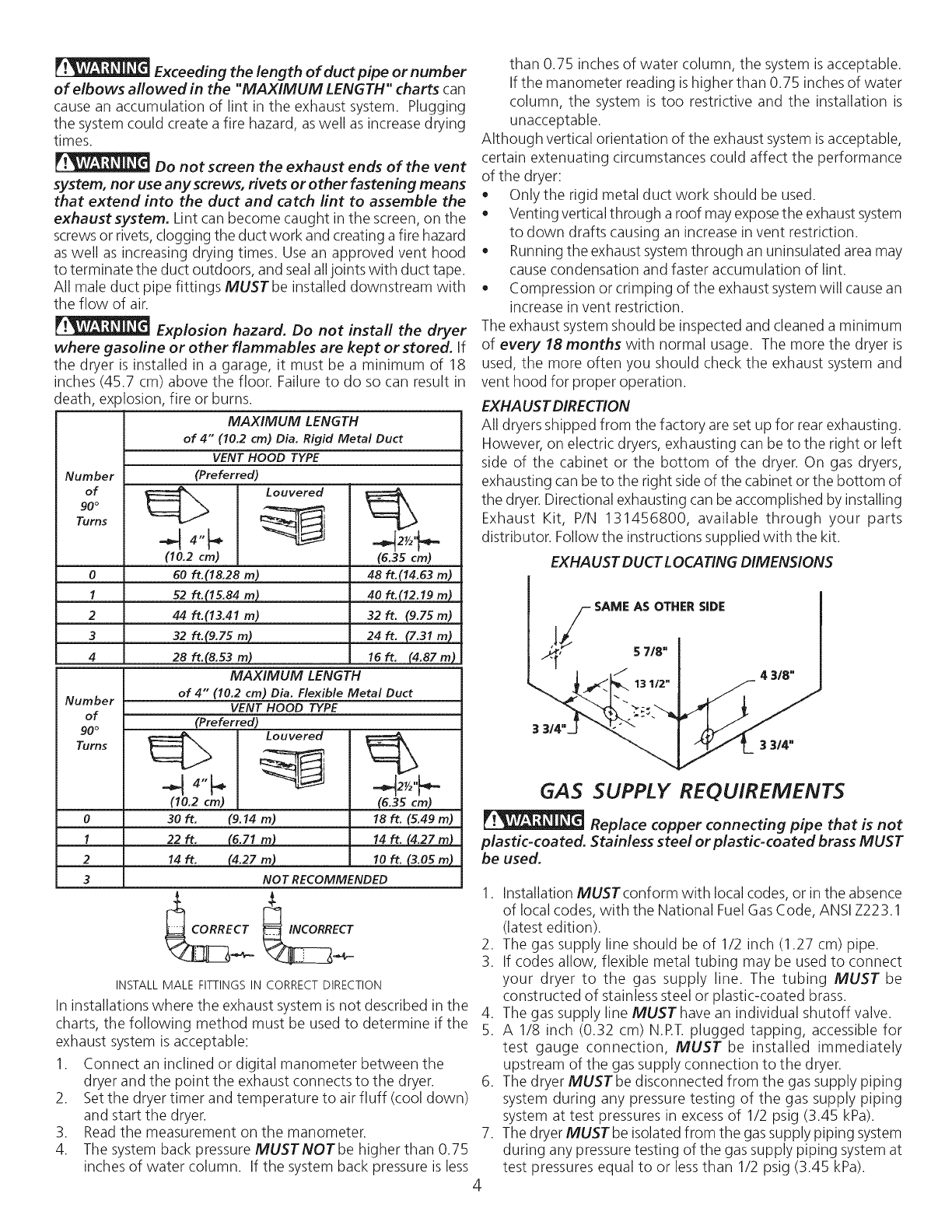
Number
of
90°
Turns
0
1
2
3
4
MAXIMUM LENGTH
of 4" (10.2 cm) Dia. Rigid Metal Duct
VENT HOOD TYPE
(Preferred)
Louvered
(10.2 cm)
60 ft.(18.28 m)
52 ft.(15.84 m)
44 ft.(13.41 m)
32 ft.(9.75 m)
28 ft.(8.53 m)
MAXIMUM LENGTH
of 4" (10.2 cm) Dia. Flexible Metal Duct
2½'_.-
(6.35 cm)
48 ft.(14.63m)
40 ft.(12.19m)
32ft. (9.75m)
24 ft. (7.31 m)
16ft. (4.87m)
Number
VENT HOOD TYPE
of (Preferred)
(10.2 cm) (6.35 cm)
0 30 ft. (9.14 m) 18 ft. (5.49 m)
1 22 ft. (6.71 m) 14 ft. (4.27 m)
2 14 ft. (4.27 m) 10 ft. (3.05 m)
3 NOT RECOMMENDED
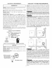
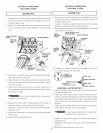
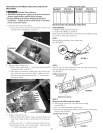
INSTALL MALE FITTINGS IN CORRECTDIRECTION
In installations where the exhaust system is not described in the
charts, the following method must be used to determine if the
exhaust system is acceptable:
1. Connect an inclined or digital manometer between the
dryer and the point the exhaust connects to the dryer.
2. Set the dryer timer and temperature to air fluff (cool down)
and start the dryer.
3. Read the measurement on the manometer.
4. The system back pressure MUSTNOTbe higher than 0.75
inches of water column. If the system back pressure is less
than 0.75 inches of water column, the system is acceptable.
If the manometer reading is higher than 0.75 inches of water
column, the system is too restrictive and the installation is
unacceptable.
Although vertical orientation of the exhaust system isacceptable,
certain extenuating circumstances could affect the performance
of the dryer:
• Only the rigid metal duct work should be used.
Venting vertical through a roof may exposethe exhaust system
to down drafts causing an increase in vent restriction.
Running the exhaust system through an uninsulated area may
cause condensation and faster accumulation of lint.
Compression or crimping of the exhaust system will cause an
increase in vent restriction.
The exhaust system should be inspected and cleaned a minimum
of every 18 months with normal usage. The more the dryer is
used, the more often you should check the exhaust system and
vent hood for proper operation.
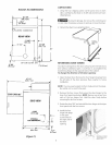
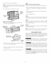
EXHAUST DIRECTION
All dryers shipped from the factory are set up for rear exhausting.
However, on electric dryers, exhausting can be to the right or left
side of the cabinet or the bottom of the dryer. On gas dryers,
exhausting can be to the right side of the cabinet or the bottom of
the dryer. Directional exhausting can be accomplished by installing
Exhaust Kit, P/N 131456800, available through your parts
distributor. Follow the instructions supplied with the kit.
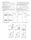
EXHA LISTDUCT LOCATINGDIMENSIONS
SAME AS OTHER SIDE
GAS SUPPLY REQUIREMENTS
Replace copper connecting pipe that is not
plastic-coated. Stainless steel or plastic-coated brass MUST
be used.
1. Installation MUST conform with local codes, or in the absence
of local codes, with the National Fuel GasCode, ANSI Z223.1
(latest edition).
2. The gas supply line should be of 1/2 inch (1.27 cm) pipe.
3. If codes allow, flexible metal tubing may be used to connect
your dryer to the gas supply line. The tubing MUST be
constructed of stainless steel or plastic-coated brass.
4. The gas supply line MUSThave an individual shutoff valve.
5. A 1/8 inch (0.32 cm) N.RT. plugged tapping, accessible for
test gauge connection, MUST be installed immediately
upstream of the gas supply connection to the dryer.
6. The dryer MUSTbe disconnected from the gas supply piping
system during any pressure testing of the gas supply piping
system at test pressures in excessof 1/2 psig (3.45 kPa).
7. The dryer MUSTbe isolated from the gas supply piping system
during any pressure testing of the gas supply piping system at
test pressures equal to or less than 1/2 psig (3.45 kPa).