


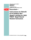

a. Plug MTA 82 into the MTA 82 connector on the balance board, remove the wire tray
covers, then connect the four individual wires from the connector to the TBA terminal
strip as follows:
• Connect the blue/white wire from MTA 82 - pin 4 to TBA #7 (ground).
• Connect the blue/red wire from MTA 82 - pin 3 to TBA #103 (+5 V).
• Connect the blue/orange wire from MTA 82 - pin 6 to TBA #104 (+12 V).
• Connect the blue/black wire from MTA 82 - pin 5 to TBA #105 (-12 V).
b. Plug MTA 84 into the MTA 84 connector on the balance board. This connector has only
one blue/black wire. Connect this wire from MTA 84 - pin 4 to TBA #64.
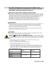
c. Plug MTA 85 into the MTA 85 connector on the balance board, then connect the two
wires from this connector to the TBA terminal strip as follows:
• Connect the blue/black wire from MTA 85 - pin 8 to TBA #115.
• Connect the blue/white wire from MTA 85 - pin 9 to TBA #7.
15. Locate the accelerometer harness threaded to the rear electric box in step 11. Connect this
harness to the four pin MTA 83 plug as follows:
Extra pins are included in case any of the pins on the accelerometer cable are damaged
during the threading process.
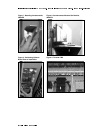
16. Find the four pin connector labeled MTA 83.
17. Push each pin into the connector as follows:
• White wire to MTA 83 - pin 1.
• Red wire to MTA 83 - pin 2.
• Black wire to MTA 83 - pin 4.
• Attach the shielding wire to a machine ground.
18. Plug the MTA 83 connector into the matching MTA 83 connector on the balance board.
19. Remove the tray cover from the wire tray above TBA.
20. Locate the orange/black wire that is taped together with several other spare wires.
21. Separate this wire from the other spare wires and connect to TBA #115.
22. Route all loose wires through the nearest wire tray and reinstall the tray covers.
23. Close rear electric box door.
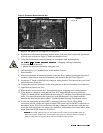
24. Open processor box door and locate the orange/black wire that is also taped together with
several other spare wires.
25. Find the orange wire shipped with the kit. This wire has a butt splice connector on one end
and a processor pin on the other.
26. Splice this orange wire to the end of the orange/black wire located in the processor box.
27. Disconnect the MTA 38 connector from the processor board.
28. Push the pin on the orange wire through the MTA 38 connector at pin 4.
29. Reinstall MTA 38 connector on the processor board and close the processor box door.
30. Restore power to machine.
31. Set VOM meter to the 0-5 VDC scale (or the closest range on your meter).
32. Slide meter leads into contact with the black wire pin and the red wire pin at the
accelerometer connector.