


Design and specifi cations are each subject to change without notice. Ask factory for the current technical specifi cations before purchase and/or use.
Should a safety concern arise regarding this product, please be sure to contact us immediately.
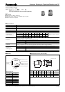
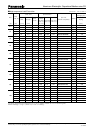
Aluminum Electrolytic Capacitors/ FK
22
Capacitance (µF)
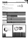
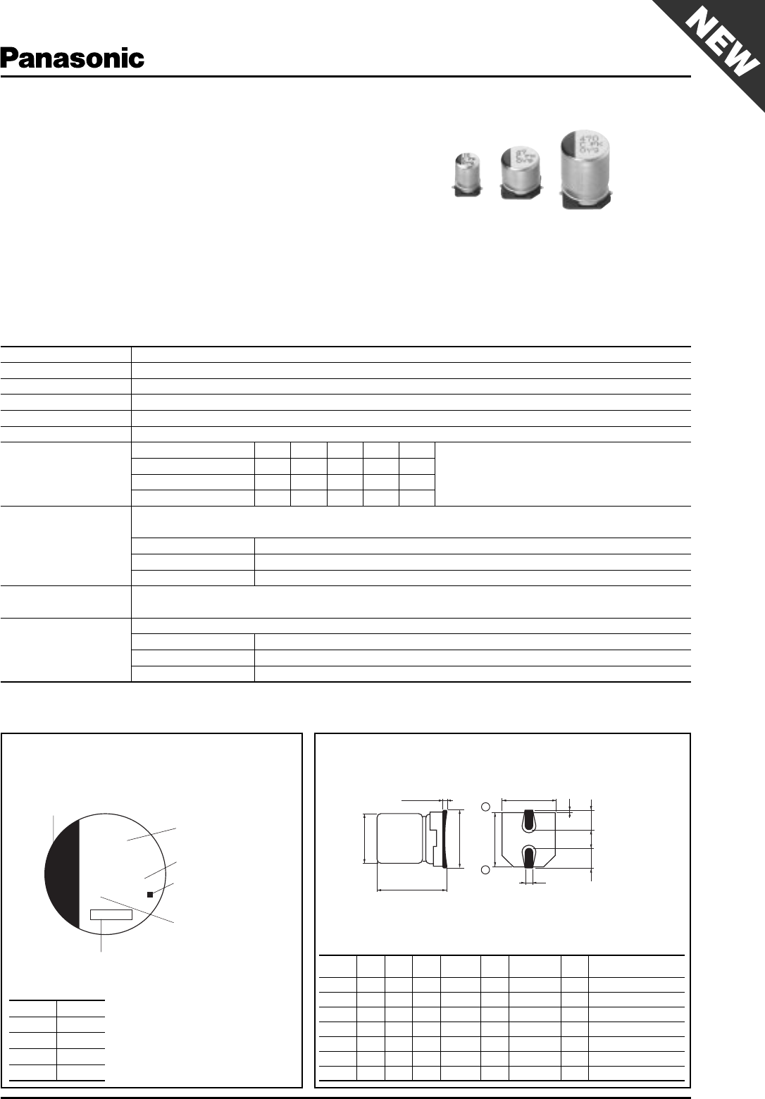
Rated Voltage Mark
Series identification
Mark for Lead-Free
Products Black Dot
(Square)
Lot number
Negative polarity
marking (–)
jFK
0.3 max.
A±0.2
W
( )reference size
L±0.3
φD±0.5
H
B±0.2
(I)
K
(P)
(I)
+
–
■ Features
●
Endurance: 2000 h at 105 °C
●
Low impedance (40 % to 60 % less than FC series)
Miniaturized (30 % to 50 % less than FC series)
●
Vibration-proof product is available upon request. (
φ
8
<
)
●
RoHS directive compliant
Surface Mount Type
Series:
FK
Type:
V
FK
High temperature Lead-Free refl ow(suffi x:A
✽
)
■ Specifi cations
Category Temp. Range –55 °C to +105 °C
Rated W.V.Range 6.3 V.DC to 35 V.DC
Nominal Cap.Range 4.7 µF to 1500 µF
Capacitance Tolerance ±20 % (120 Hz/+20 °C)
DC Leakage Cur rent I
<
0.01 CV or 3 (µA) After 2 minutes (Whichever is greater)
tan
δ
Please see the attached High temperature lead-free refl ow products list.
Characteristics
at Low Temperature
W.V. (V) 6.3 10 16 25 35
(Impedance ratio at 120 Hz)
Z(–25 °C)/Z(+20 °C) 22222
Z(–40 °C)/Z(+20 °C) 33333
Z(–55 °C)/Z(+20 °C) 44433
Endurance
After applying rated working voltage for 2000 hours at +105 °C±2 °C and then being stabilized at +20 °C,
Capacitors shall meet the following limits.
Capacitance change ±30 % of initial measured value
tan
δ
<
200 % of initial specifi ed value
DC leakage current
<
initial specifi ed value
Shelf Life
After storage for 1000 hours at +105 °C±2 °C with no voltage applied and then being stabilized
at +20 °C, capacitors shall meet the limits specifi ed in Endurance. (With voltage treatment)
Resistance to
Soldering Heat
After refl ow soldering and then being stabilized at +20 °C, capacitor shall meet the following limits.
Capacitance change ±10 % of initial measured value
tan
δ
<
initial specifi ed value
DC leakage current
<
initial specifi ed value
■ Di men sions in mm (not to scale) ■ Marking
Example:6.3 V 22 µF
Marking color : BLACK
Rated Voltage Mark
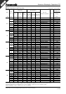
(mm)
Size
code
DLA,BH max.I W P K
B4.05.84.35.5 1.8 0.65±0.1 1.0 0.35–0.20 to +0.15
C5.05.85.36.52.20.65±0.1 1.5 0.35–0.20 to +0.15
D6.35.86.67.82.60.65±0.11.80.35–0.20 to +0.15
D8 6.3 7.7 6.6 7.8 2.6 0.65±0.1 1.8 0.35–0.20 to +0.15
E8.06.28.39.53.40.65±0.1 2.2 0.35–0.20 to +0.15
F8.010.28.310.0 3.40.90±0.2 3.1 0.70±0.2
G10.010.2 10.3 12.0 3.5 0.90±0.2 4.6 0.70±0.2
j6.3 V
A10 V
C16 V
E25 V
V35 V
Jul. 2008