


P/N 20-07121-00 Rev. C Page 3
2.0 MECHANICAL INSTALLATION
CAUTION: The Mercury dispensing system is
intended to be installed by experi-
enced installers in accordance with
all applicable electrical and plumbing
codes.
Disconnect power to all laundry
machine and dispensers during
installation and/or any time the
dispenser cabinet is opened.
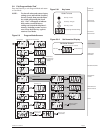
2.1 Wall Mounting Unit
To determine a suitable location to install the
dispenser, keep the following in mind:
Install close to product containers at a reasonable
height for easy service access.
When intended for Push Button Mode operation, be
sure to allow easy front panel access for the machine
operator.
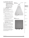
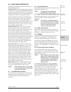
2.1.1 Drill one hole in wall for upper mounting
bracket screw wall anchor.
2.1.2 Install wall anchor and temporarily attach
bracket to the wall (do not tighten screw all
the way).
2.1.3 Level bracket using built-in level and mark
drill locations for lower mounting screw holes.
2.1.4 Swing bracket out of the way, drill lower
holes, and install lower wall anchors.
2.1.5 Screw bracket into place.
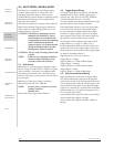
2.1.6 Lower unit onto wall mount bracket and press
down until unit locks into place. To remove
unit from bracket, depress lock button on the
top of the bracket as you lift the unit from the
mounting bracket.
2.2 Supply and Discharge Hoses
We recommend use of 3/8" ID hose for supply and
discharge hoses. Use of smaller size ID hose/tube
may results in reduced flow rates, premature pump
tube failure, or both.
The maximum combined distance for supply and
discharge hoses must not exceed 50 feet. The
maximum supply side hose distance must not exceed
15 feet. The maximum vertical height from product
container to pump must not exceed 10 feet.
Use hose clamps to secure supply and discharge
hoses to pump tube hose barbs. Route supply hose to
product pails and discharge hose to washer per
industry standard practices.
THEORY OF
OPERATION
MECHANICAL
INSTALLATION
ELECTRICAL
INSTALLATION
PROGRAMMING
USER MODE
OPERATION
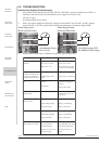
TROUBLESHOOTING
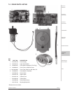
SPARE PARTS
LISTING
MAINTENANCE &
SPECIFICATIONS
INDEX
Figure 2.0
Mounting Bracket
Lock Button
Level
Figure 2.1
Unit Rear Bracket Slot