


7
GAS DRYER POWER HOOKUP
Gas Supply Requirements
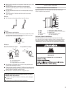
WARNING
Explosion Hazard
Use a new CSA International approved gas supply line.
Install a shut-off valve.
Securely tighten all gas connections.
If connected to LP, have a qualied person make sure
gas pressure does not exceed 13" (330 mm) water
column.
Examples of a qualied person include:
licensed heating personnel,
authorized gas company personnel, and
authorized service personnel.
Failure to do so can result in death, explosion, or re.
Gas type
Natural gas:
This dryer is equipped for use with Natural Gas. It is design-
certied by CSA International for LP (propane or butane) gases
with appropriate conversion.
Your dryer must have the correct burner for the type of gas ■
in your home. Burner information is located on the rating
plate in the door well of your dryer. If this information does
not agree with the type of gas available, please reference
the “Assistance or Service” section of the “Dryer User
Instructions.”
LP gas conversion:
Conversion must be made by a qualied technician.
No attempt shall be made to convert the dryer from the gas
specied on the model/serial rating plate for use with a different
gas without consulting the serving gas supplier.
IMPORTANT: The gas installation must conform with local codes,
or in the absence of local codes, with the National Fuel Gas
Code, ANSI Z223.1/NFPA 54 or the Canadian Natural Gas and
Propane Installation Code, CSA B149.1.
Gas supply line
1/2" NPT pipe is recommended. ■
3/8" approved tubing is acceptable for lengths under ■
20 ft. (6.1 m) if local codes and gas supplier permit.
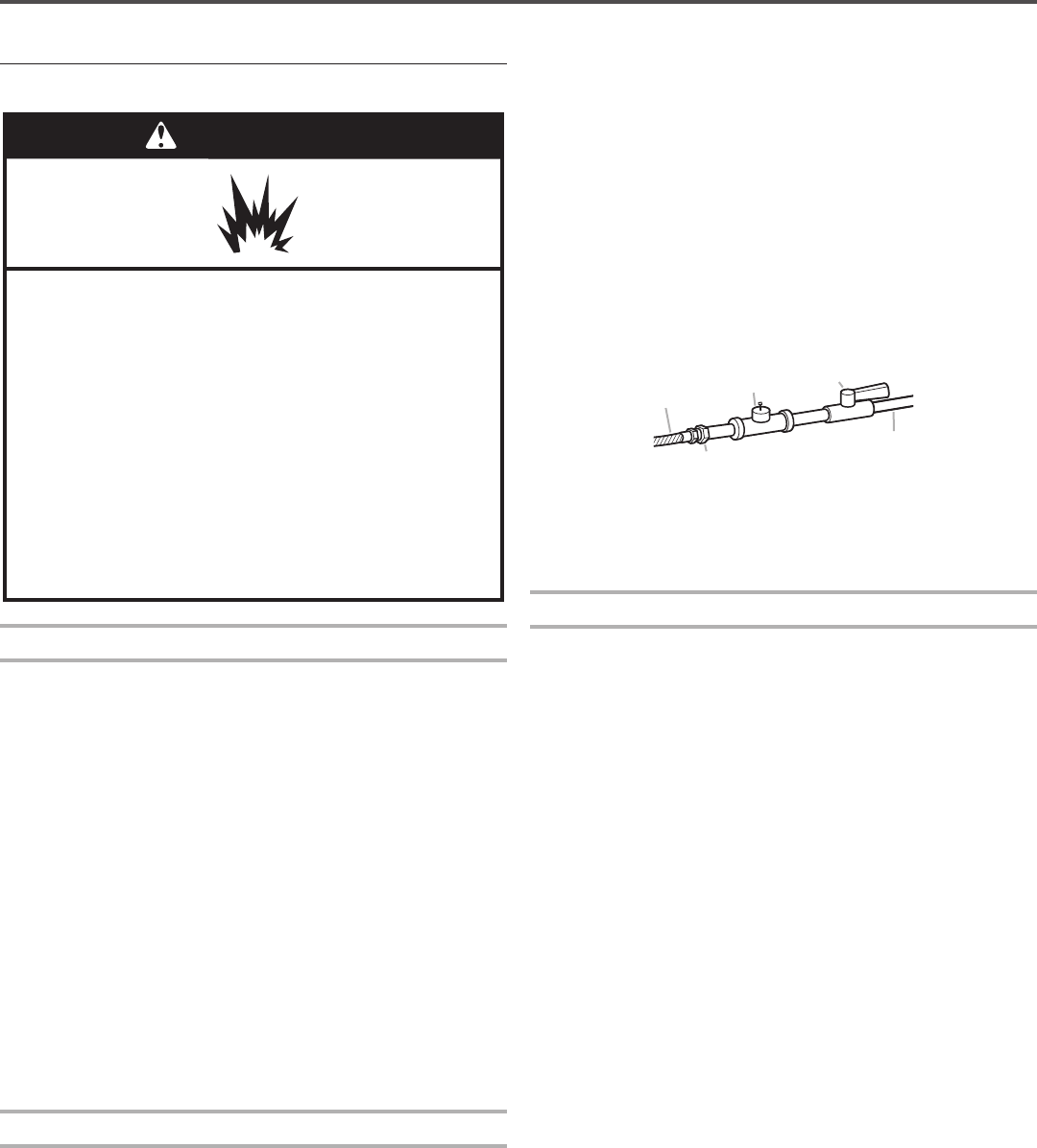
Must include 1/8" NPT minimum plugged tapping accessible ■
for test gauge connection, immediately upstream of the gas
connection to the dryer (see illustration).
Must include a shutoff valve: ■
In the U.S.A.:
An individual manual shutoff valve must be installed within
six (6) feet (1.8 m) of the dryer in accordance with the
National Fuel Gas Code, ANSI Z223.1.
In Canada:
An individual manual shutoff valve must be installed in
accordance with the B149.1, Natural Gas and Propane
Installation Code. It is recommended that an individual
manual shutoff valve be installed within six (6) feet (1.8 m)
of the dryer.
The shut off valve location should be easy to reach for opening
and closing.
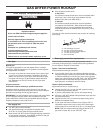
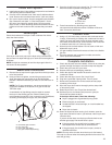
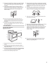
A
B
E
D
C
A. 3/8" exible gas connector
B. 3/8" pipe to are adapter tting
C. 1/8" NPT minimum plugged tapping
D. 1/2" NPT gas supply line
E. Gas shutoff valve
Gas supply connection requirements
There are many methods by which your gas dryer can be
connected to the gas supply. Listed here are some guidelines
for two different methods of connection.
Option 1 (Recommended Method)
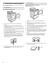
Flexible stainless steel gas connector:
If local codes permit, use a new exible stainless steel gas ■
connector (Design Certied by the American Gas Association
or CSA International) to connect your dryer to the rigid gas
supply line. Use an elbow and a 3/8" are x 3/8" NPT adapter
tting between the stainless steel gas connector and the
dryer gas pipe, as needed to prevent kinking.
Option 2 (Alternate Method)
Approved aluminum or copper tubing:
Lengths over 20 ft. (6.1 m) can use 3/8" approved tubing ■
(if codes and gas supplier permit).
If you are using Natural Gas, do not use copper tubing. ■
3/8" are x 3/8" NPT adapter tting between dryer pipe and ■
3/8" approved tubing.
Lengths over 20 ft. (6.1 m) should use larger tubing and a ■
different size adapter tting.
If your dryer has been converted to use LP gas, 3/8" LP ■
compatible copper tubing can be used. If the total length
of the supply line is more than 20 ft. (6.1 m), use larger pipe.
NOTE: Pipe joint compounds that resist the action of LP
gas must be used. Do not use TEFLON
®†
tape.
†®TEFLON is a registered trademark of E.I. Du Pont De Nemours and Company.