


12
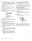
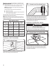
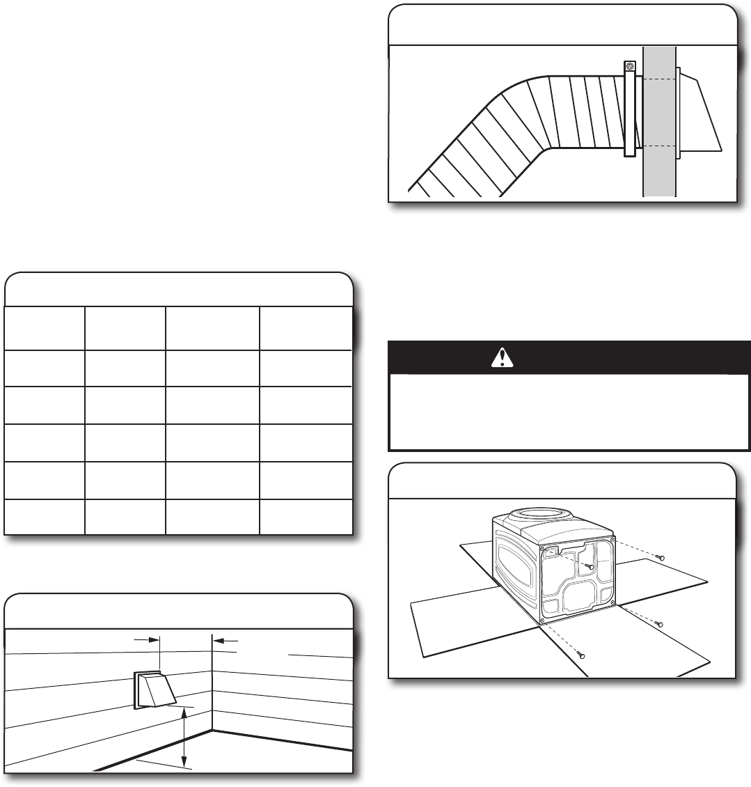
Vent system chart
Number of
90° elbows
Type
of vent
Box/louvered
hoods
Angled
hoods
1
4
3
2
0
Rigid metal
Rigid metal
Rigid metal
Rigid metal
Rigid metal
64 ft. (20 m)
54 ft. (16.5 m)
44 ft. (13.4 m)
35 ft. (10.7 m)
27 ft. (8.2 m)
58 ft. (17.7 m)
48 ft. (14.6 m)
38 ft. (11.6 m)
29 ft. (8.8 m)
21 ft. (6.4 m)
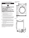
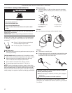
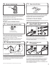
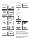
INSTALL VENT SYSTEM
12" min.
(305 mm)
12" min.
(305 mm)
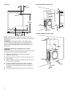
Install exhaust hood
1.
Install exhaust hood and use caulking compound to seal
exterior wall opening around exhaust hood.
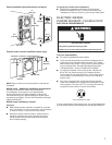
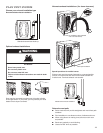
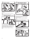
Prepare dryer for leveling legs
3.
To avoid damaging oor, use a large at piece of cardboard
from dryer carton; place under entire back edge of dryer.
Firmly grasp dryer body (not console panel) and gently lay
dryer down on cardboard.
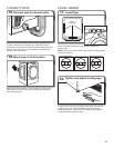
INSTALL LEVELING LEGS
WARNING
Excessive Weight Hazard
Use two or more people to move and install dryer.
Failure to do so can result in back or other injury.
Connect vent to exhaust hood
2.
Vent must t over the exhaust hood. Secure vent to exhaust
hood with 4" (102 mm) clamp. Run vent to dryer location
using straightest path possible. Avoid 90° turns. Use clamps
to seal all joints. Do not use duct tape, screws, or other
fastening devices that extend into interior of vent to secure
vent, because they can catch lint.
The Vent system chart provides venting requirements that will
help achieve best drying performance.
NOTE: Side and bottom exhaust installation have a 90° turn
inside the dryer. To determine maximum exhaust length, add
on 90° turn to the chart.
Determine vent length and elbows needed for best
drying performance:
Use following Vent system chart to determine type of vent ■
material and hood combinations acceptable to use.
NOTE: Do not use vent runs longer than those specied
in Vent system chart.
Exhaust systems longer than those specied will:
Shorten life of dryer. ■
Reduce performance, resulting in longer drying times ■
and increased energy usage.