


16
NOTE: The following kits for close clearance alternate
installations are available for purchase. Please see the
“Assistance or Service” section of this manual to order.
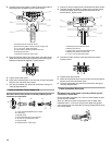
■ Over-the-Top Installation:
Part Number 4396028
■ Periscope Installation (For use with dryer vent to wall vent
mismatch):
Part Number 4396037 - 0" (0 cm) to 18" (45.72 cm)
mismatch
Part Number 4396011 - 18" (45.72 cm) to 29" (73.66 cm)
mismatch
Part Number 4396014 - 29" (73.66 cm) to 50" (127 cm)
mismatch
Special provisions for mobile home installations
The exhaust vent must be securely fastened to a noncombustible
portion of the mobile home structure and must not terminate
beneath the mobile home. Terminate the exhaust vent outside.
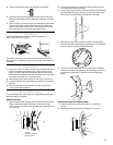
Determine vent path
■ Select the route that will provide the straightest and most
direct path outdoors.
■ Plan the installation to use the fewest number of elbows and
turns.
■ When using elbows or making turns, allow as much room as
possible.
■ Bend vent gradually to avoid kinking.
■ Use the fewest 90° turns possible.
Determine vent length and elbows needed for best
drying performance
■ Use the following Vent system chart to determine type of vent
material and hood combinations acceptable to use.
NOTE: Do not use vent runs longer than those specified in
the Vent system chart. Exhaust systems longer than those
specified will:
■ Shorten the life of the dryer.
■ Reduce performance, resulting in longer drying times and
increased energy usage.
The Vent system chart provides venting requirements that will
help to achieve the best drying performance.
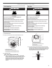
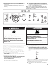
Vent system chart
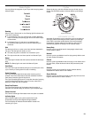
NOTE: Side and bottom exhaust installations have a 90º turn
inside the dryer. To determine maximum exhaust length, add one
90º turn to the chart.
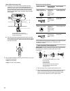
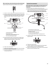
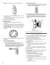
Install Vent System
1. Install exhaust hood. Use caulking compound to seal exterior
wall opening around exhaust hood.
2. Connect vent to exhaust hood. Vent must fit inside exhaust
hood. Secure vent to exhaust hood with 4" (10.2 cm) clamp.
3. Run vent to dryer location. Use the straightest path possible.
See “Determine vent path” in “Plan Vent System.” Avoid 90º
turns. Use clamps to seal all joints. Do not use duct tape,
screws or other fastening devices that extend into the interior
of the vent to secure vent.
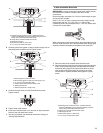
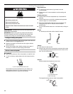
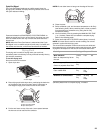
Install Leveling Legs
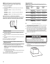
1. To protect the floor, use a large flat piece of cardboard from
the dryer carton. Place cardboard under the entire back edge
of the dryer.
2. Firmly grasp the body of the dryer (not the console panel).
Gently lay the dryer on the cardboard. See illustration.
Number of
90º turns
or elbows
Type of
vent
Box or
louvered
hoods
Angled
hoods
0 Rigid metal
Flexible metal
64 ft (20 m)
36 ft (11 m)
58 ft (17.7 m)
28 ft (8.5 m)
1 Rigid metal
Flexible metal
54 ft (16.5 m)
31 ft (9.4 m)
48 ft (14.6 m)
23 ft (7 m)
2 Rigid metal
Flexible metal
44 ft (13.4 m)
27 ft (8.2 m)
38 ft (11.6 m)
19 ft (5.8 m)
3 Rigid metal
Flexible metal
35 ft (10.7 m)
25 ft (7.6 m)
29 ft (8.8 m)
17 ft (5.2 m)
4 Rigid metal
Flexible metal
27 ft (8.2 m)
23 ft (7 m)
21 ft (6.4 m)
15 ft (4.6 m)
WARNING
Excessive Weight Hazard
Use two or more people to move and install dryer.
Failure to do so can result in back or other injury.