


Manufacturers Supply Inc dba Majestic Appliances © 2004
Manufacturers Supply Inc dba Majestic Appliances © 2004
Installing/Removing
Getting things ready to install your
appliance (continued)
Plumbing - Water, Drains
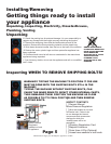
WATER CONNECTION
1. This appliance can be used with either hot/cold or cold/cold connections.
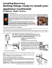
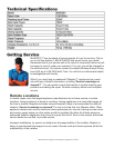
2. The hoses supplied have either a straight end or an elbow end. The elbow
end is meant to connect to the washer. Be sure to connect the hot hose to
the hot side of the appliance itself, the cold side to the cold connection.
(See picture) The straight end to the 3/4” BSP standard hose bib thread.
3. MAKE SURE WASHERS ARE INSTALLED IN EACH END OF THE SUPPLY
HOSES.
4. Ensure that water connections are free from debris or sediment.
6. BRASS PRESSURE REDUCERS MUST BE INSTALLED TO PROTECT
COMPONENTS INSIDE THE APPLIANCE.IMPORTANT ! CHECK THREADS
ON THE MACHINE, THE BRASS PRESSUREREDUCERS AND THE SUPPLY
HOSES TO ENSURE THEY ARE CLEAN. DO NOTUSE EXCESSIVE FORCES.
TIGHTEN BY HAND. DO NOT USE POWER TOOLS.
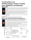
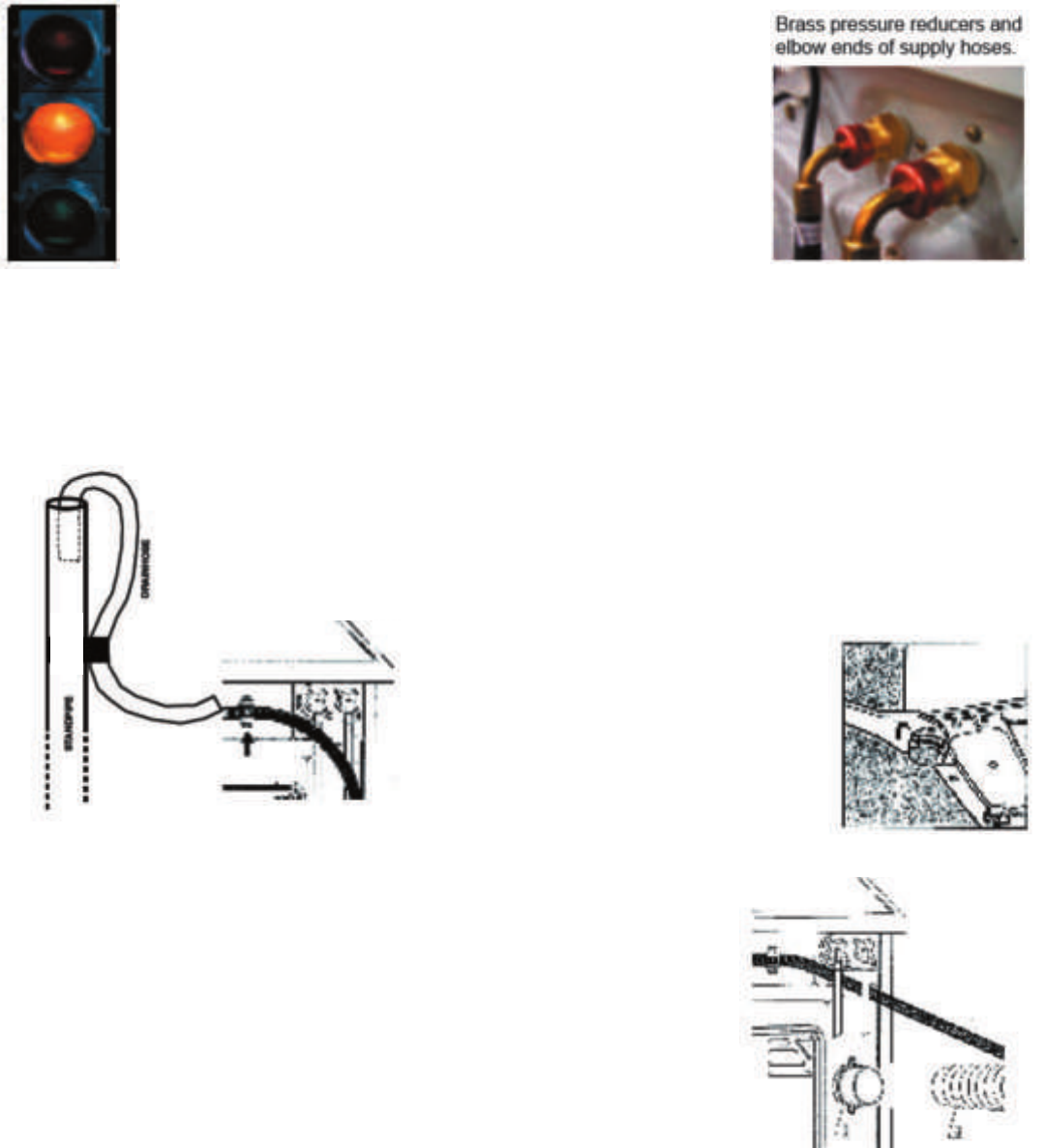
Connection of the drain hose to standpipe
• Outlet end of drain hose (See gure 2) must be at least 20” above bottom of washer. Do NOT block top of standpipe closes with tape
or other materials. An air break must be provided at the standpipe to avoid siphoning.
• Connect the drain hose to a standpipe (with internal diameter of at least 3.2 cm or 1 1/4” min. diameter) with a minimum carry away
volume of 7 gallons. The top of the standpipe must be 20” minimum from the botton of the appliance. Place drain hose for drainage into
a sink tub or standpipe, ensuring that there are no kinks or bends. The free end must be at a height of 80 cm (31 1/2”) from the oor,
the hose must be xed in the appropriate hook on the upper part of the back panel (g.4)
DO NOT INSERT THE END IF THE DRAIN HOSE MORE THAN
6” INTO THE STANDPIPE. INSERTING MORE MAY CAUSE THE
APPLIANCES TO HAVE INSUFFICIENT DRAINAGE.
CORRECT LEVELING OF UNIT IS
ESSENTIAL
It is important for the machine to be
perfectly level. The angle of inclination on
the work surface must not be more than
2 degrees. For this reason the machine is
tted with adjustable feet used for leveling
the machine before use. In the case of
carpeted ooring, remember to check that
the ventilation in the support area is not
plugged.
Exhaust Duct Installation
• Check that all ducting is lint free. Secure ducting with clamps or metal
tape.
• The exhaust duct must end with an approved exhaust vent hood with
swing out dampers or appropriate louvers.
• Flex or rigid metalic ducting is recommended.
• Exhaust duct should be short and straight and slope downwards and
away from the appliance. Long exhaust duct runs can increase drying
time and collect lint.
IMPORTANT! THE EXHAUST DUCT SHOULD NOT BE INSERTED INTO A
CHIMNEY WALL, CEILING OR CONCEALED SPACE OF STRUCTURE.