Inspection and Installation
26
3.9 Refrigeration Piping Connections
3.9.1 Piping Guidelines
Indoor units and condensers both ship with nitrogen holding charges. Do not vent the condenser until
all refrigerant piping is in place, ready for connection to indoor unit and condenser.
• Use copper piping with a brazing alloy with a minimum temperature of 1350°F (732°C), such as
Sil-Fos. Use a flow of dry nitrogen through the piping to prevent the formation of copper oxide
scale inside the piping. Avoid soft solders such as 50/50 or 95/5.
• Isolate piping from building using vibration isolating supports.
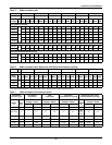
• Refer to indoor unit user manual for appropriate piping sizes.
• Install traps on the hot gas (discharge) lines at the bottom of any rise over 5 feet high. If the rise
exceeds 25 feet (7.5m), then install a trap in 20 foot (6m) increments or evenly divided.
• Pitch horizontal hot gas piping at a minimum rate of 1/2" per 10 ft. (42mm per 10m) so that grav-
ity will aid in moving oil in the direction of refrigerant/oil flow.
• Consult factory if Lee-Temp condenser is located more than 15 ft (4.6m) below the evaporator or if
Fan Speed/VFD Control Condenser is located more than 30 ft. (9.2m) below the evaporator.
• Consult factory if piping run exceeds 150 feet (46m) equivalent length.
• Keep piping clean and dry, especially on units with POE oil (R407C or R22 refrigerant).
• Avoid piping runs through noise-sensitive areas.
• Do not run piping directly in front of indoor unit discharge airstream.
• Refrigerant oil – do not mix oil types or viscosities. Consult indoor unit for refrigerant type and oil
requirements.
!
WARNING
Risk of explosive discharge from high-pressure refrigerant. Can cause equipment damage,
injury or death. Relieve pressure before working with piping.
!
WARNING
Risk of refrigerant system rupture or explosion from overpressurization. Can cause
equipment damage, injury or death.
If a pressure relief device is not provided with the condenser unit, the system installer must
provide and install a discharge pressure relief valve rated for a maximum of 500 psig (34bar)
in the high side refrigerant circuit. Do not install a shutoff valve between the compressor and
the field installed relief valve.
One or more additional pressure relief valves are required downstream of any and all field
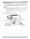
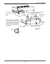
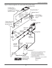
installed isolation valves as shown in Figures 2 and 24. Do not isolate any refrigerant
circuits from overpressurization protection.
NOTE
POE (polyol ester) oil, required with R407C and used with some R22 systems, is much more
hygroscopic than mineral oils. This means that POE oil absorbs water at a much faster rate
when exposed to air than previously used mineral oils. Because water is the enemy of a reliable
refrigeration system, extreme care must be used when opening systems during installation or
service. If water is absorbed into the POE oil, it will not be easily removed and will not be
removed through the normal evacuation process. If the oil is too wet, it may require an oil
change. POE oils also have a property that makes them act as a solvent in a refrigeration
system. Maintaining system cleanliness is extremely important because the oil will tend to
bring any foreign matter back to the compressor.
NOTE
Failure to use compressor oils recommended by compressor manufacturer will void compressor
warranty. Consult Liebert or compressor manufacturer for further recommendations or if you
have questions about compressor oils.
Refer to ASHRAE Refrigeration Handbook for general good practices for refrigeration piping.
A pressure relief valve is provided with Liebert Lee-Temp condensers. A fusible plug is
provided on Liebert Fan Speed Control and VFD condensers. The Liebert indoor cooling unit
has a factory-installed high-pressure safety switch in the high side refrigerant circuit.


