


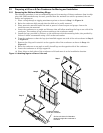
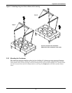
Inspection and Installation
20
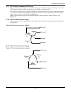
3.6.2 Low Voltage Control Wiring
NOTICE
Risk of control malfunction. Can cause improper unit operation. Make sure that all low
voltage electrical wiring has been performed per the schematic diagram provided and that all
low voltage wiring connections are tight.
A control interlock between the condenser and the indoor cooling units is required. Field-supplied cop-
per wire (Class 1 for TCDV models and Class 2 for all other condenser models) is required for connec-
tion between like-numbered terminals 70 & 71 on both units. Wiring must be sized so that the voltage
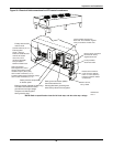
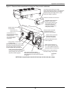
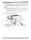
drop in the circuit does not exceed 1 volt. See Figures 19, 20 and 21 and indoor unit manual for loca-
tion of terminals on condensers and indoor units.
3.6.3 Low Voltage Monitoring Wiring—TCDV Only
Condensers with monitoring terminals may be wired with Class 1 copper wire to the indoor cooling
unit or other monitoring panel. Wiring must be sized so that the voltage drop in the circuit does not
exceed 1 volt. Dry contacts close when a monitored event occurs. Consult condenser electrical sche-
matic, supplied with the unit, for details.
Contact closure on VFD Drive monitoring terminals indicates a permanent VFD fault. A factory-pro-
grammed VFD must be used as the replacement.
Contact closure on TVSS monitoring terminals may indicate unit trouble ranging from electrical sup-
ply issues to TVSS replacement required. A properly trained and qualified electrician is required.
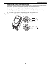
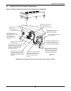
3.7 Electrical Connections
Electrical service is required for all models. Electrical service shall conform to national and local elec-
trical codes. Refer to equipment nameplate regarding wire size and circuit protection requirements.
Refer to electrical schematic when making connections. Refer to Figures 19, 20 and 21 for electrical
service entrances into unit.
A manual electrical disconnect switch should be installed in accordance with local codes. Consult local
codes for external disconnect requirements.
NOTICE
Installation and service of this equipment should be done only by properly trained and
qualified personnel who have been specially trained in the installation of air conditioning
equipment.
NOTICE
Use copper wiring only. Make sure that all conections are tight.
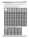
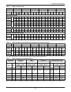
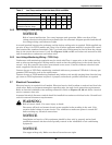
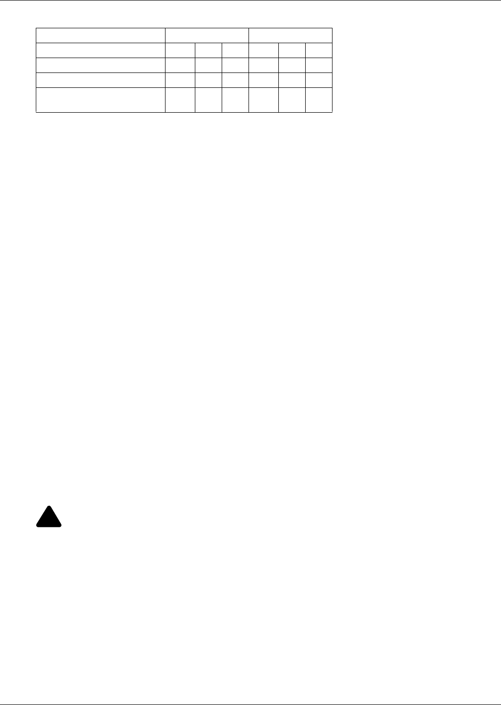
Table 8 Lee-Temp receiver electrical data, 50Hz and 60Hz
Rated Voltage - Single Phase 120 200/208/230
Watts/Receiver 150 300 450 150 300 450
Full Load Amps 1.4 2.8 4.2 0.7 1.4 2.1
Wire Size Amps 1.8 3.5 5.3 0.9 1.8 2.7
Maximum Overcurrent
Protection Device, Amps
15 15 15 15 15 15
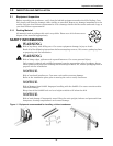
!
WARNING
Risk of electric shock. Can cause injury or death.
Disconnect all local and remote electric power supplies before working in the unit. Unit
contains lethal voltage in some circuits. Use voltmeter to make sure power is turned Off
before making any electrical connections.