


GB
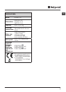
7
570
min
815
540
595
820 ÷ 900
600 min
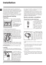
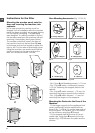
Using the Drilling Template.
- To trace the positions of the holes on the left-
hand side of the panel, align the drilling tem-
plate to the top left side of the panel using the
lines traced on the extremities as a reference.
- To trace the positions of the holes on the
right-hand side of the panel, align the drilling
template to the top right side of the panel.
- Use an appropriately sized router to mill the
holes for the two hinges, the rubber plug and
the magnet.
Mounding the Parts onto the Wooden
Panel (Door).
- Insert the hinges into the holes (the movable
part of the hinge must be positioned facing
away from the panel) and fasten them with
the 4 type A screws.
- Insert the magnet into the top hole on the
opposite side of the hinges and fasten it with
the two type B screws.
- Insert the rubber plug into the bottom hole.
The panel is now ready to be mounted onto
the machine.
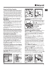
Mounting the Panel into the machine.
Insert the nib of the hinge (indicated by the arrow
in fig. 2) into the hole for the hinge and push the
panel towards the front of the machine. Fasten
the two hinges with the type D screws.
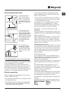
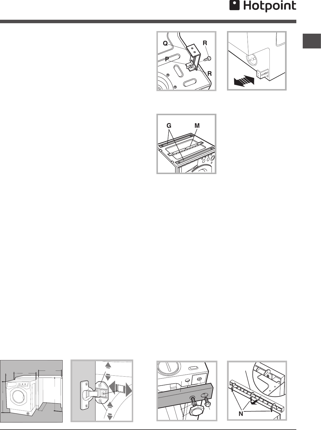
Fastening the plinth guide.
If the machine is installed at the end of a set
of modular cabinets, mount either one or both
of the guides for the base molding (as shown
in fig. 8). Adjust them for depth based on the
position of the base molding, and, if necessa-
ry, fasten the base to the guides (fig. 9). This is
how to assemble the plinth guide (fig. 8):
Fasten angle P using screw R, insert plinth
guide Q into the special slot and once it is
in the desired position, lock it in place using
angle P and screw R.
Inserting the machine into the Cabinet.
- Push the machine into the opening, aligning
it with the cabinets (fig. 6).
- Regulate the adjustable feet to raise the
machine to the appropriate height.
- To adjust the position of the wooden panel
in both the vertical and horizontal directions,
use the C and D screws, as shown in fig. 7.
Important: close the lower part of the ap-
pliance front by ensuring that the plinth rests
against the floor.
Fig. 8 Fig. 9
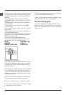
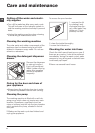
Accessories provided for the height
adjustment.
The following can be found
inside the polystyrene lid
(fig. 10): 2 crossbars (G), 1
strip (M)
the following can be found
inside the appliance drum:
4 additional feet (H),
4 screws (I),
4 screws (R),
4 nuts (L),
2 plinth guides (Q)
Adjusting the appliance height.
The height of the appliance can be adjusted (from
815 mm to 835 mm), by turning the 4 feet.
Should you require the appliance to be placed
higher than the above height, you need to use
the following accessories to raise it to up to
870 mm:
the two crossbars (G); the 4 feet (H); the 4
screws (I); the 4 nuts (L) then perform the fol-
lowing operations (fig. 11):
remove the 4 original feet, place a crossbar G
at the front of the appliance, fastening it in pla-
ce using screws I (screwing them in where the
original feet were) then insert the new feet H.
Repeat the same operation at the back of the
appliance.
Now adjust feet H to raise or lower the applian-
ce from 835 mm to 870 mm.
Once you have reached the desired height, lock
nuts L onto crossbar G.
To adjust the appliance to a height between
870 mm and 900 mm, you need to mount
strip M, adjusting feet H to the required height.
Insert the strip as follows:
loosen the three screws N situated at the front
of the Top cover of the appliance, insert strip M
as shown in fig. 12, then fasten screws N.
D
C
C
Fig. 6 Fig. 7
L
I
H
G
M
Fig. 11 Fig. 12
Fig. 10