


American Metal Ware 87710E Coffee Urn Page 19
Disassembly
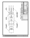
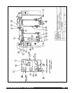
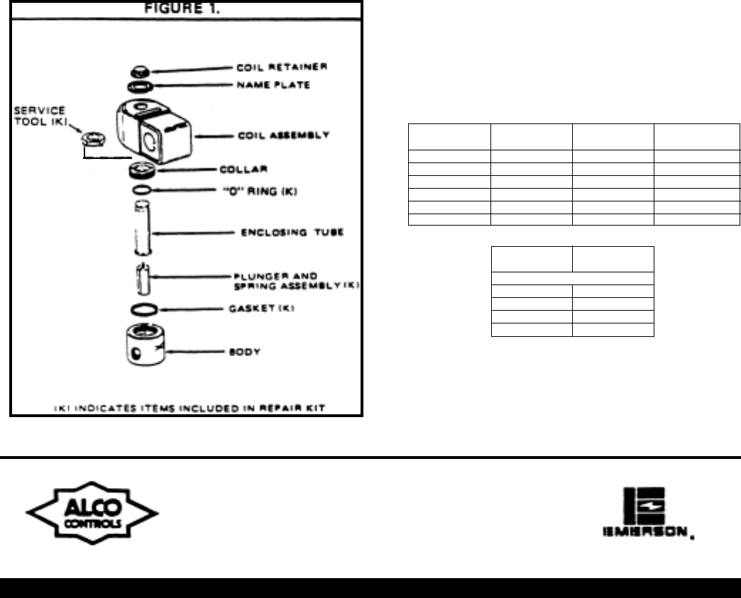
Disassemble in the same general order as indicated in exploded -
view illustrations except as noted in the following steps:
1.
2.
3.
Assembly
1.
2.
3.
Troubleshooting
1.
2.
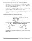
De-pressurize valve and disconnect electrical power source.
To remove solenoid coil:
Insert small screwdriver into gap in voltage nameplate. Slide
screwdriver tip under coil retainer and snap off. If replacing
coil, use knife to separate adhesive-backed valve nameplate
from coil. Keep valve nameplate.
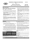
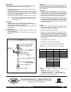
To remove collar, use service tool X11981-1 shown in Figure 1
Note: Do NOT lose nameplate, as it is extremely important
if it becomes necessary to order a parts kit, coil or
duplicate valve.
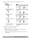
Assemble in the reverse general order of disassembly.
Lubricate gasket and “O” ring sparingly with a compatible
lubricant such as a Silicon base lubricant.
All moving parts must move freely over the full length of its
intended travel.
Check system fuses, electrical wiring and system source
voltage as specified.
Is flow direction arrow on valve the same as system flow
direction?
Cleaning
As with all valves, it may become necessary to clean them
periodically to keep them in peak operating condition. Any
cleaning methods or fluids used should be compatible with
valve materials.
Inspection
1.
2.
Testing
1.
2.
3.
4.
5.
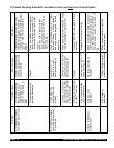
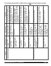
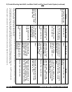
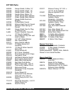
Repair Kits - The following Repair Kits are available.
Coils
1.
2.
3.
All moving parts and elastomers should be clean in
appearance without permanent set; springs should be
free of corrosion. If any appear damaged, replace them
with a parts kit which contains all moving parts
necessary to rebuild valve to an “as new” condition.
Inspect enclosing tube assembly for wear, exterior dents
or other conditions which would impair free movement of
the poppet and/or plunger assembly. Its interior should
be clean and free from any obstructions. Be especially
critical of its valve seat.
Apply correct voltage to valve solenoid and cycle
solenoid several times. A distinct click should be heard
each time the solenoid is energized.
Pressurize valve and check for leaks.
Note: Alco solenoid valves are equipped with a
continuous-duty solenoid coil, which when energized for
an extended period of time becomes hot to the touch.
This is a safe operating temperature. Any excessive
heating will be indicated by smoke and odor of burning
coil insulation.
Are all system relays operating?
Is system source pressure as specified?
Are all system components free from obstruction?
Junction box (AMG) is supplied as standard on all
valves.
The following coil housings are available:
a. Conduit Connection (AMC) c. Open Frame (AMF)
b. GROMMET 18” Leads (AML) d. Spade Connection (AMS)
Use only Alco coils on Alco valves.
Alco Controls Division • Emerson Electric Co.
P.O. Box 12700 • St. Louis, Missouri 63141 • 314-569-4500
Customer Service • 314-569-4666
Valve
Series
202CB -B
202CB -F
202CB -N
202CB -P
202CB -T
202CB -V
Kit
Part No.
K-1063
K-1066
K-1067
K-1064
K-1068
K-1065
Valve
Series
204CD -B
204CD -F
204CD -N
204CD -P
204CD -T
204CD -V
Kit
Part No.
K-1072
K-1075
K-1073
K-1076
K-1077
K-1074
Valve
Series
204CD -B
204CD -V
204CD -T
204CD -P
Kit
Part No.
K-1162
K-1164
K-1167
K-1166
For 1/4” Orifice Only