


2 3A1332A
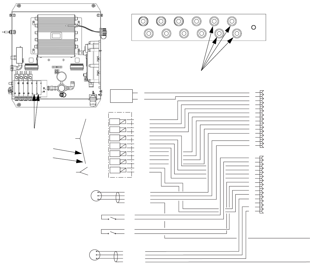
Install the Solenoid Valves
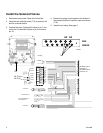
1. Disconnect main power. Open the Control Box.
2. Install the two solenoid valves (713) in positions A2
and A3 as shown below.
3. Connect the wires. Solenoid A2: black to pin 7 and
red to pin 8. Solenoid A3: black to pin 9 and red to
pin 10.
4. Remove the plugs from the ports at the bottom of
the solenoid manifold. Install the male connectors
(718).
5. Install the air tubing. See page 3.
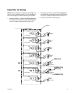
PWR (RED)
COM (BLACK)
SIG (WHITE)
SHIELD/GRN
FLOW METER A
FLOW METER B
3X CABLE
BLACK
RED
BLACK
RED
BLACK
RED
BLACK
RED
BLACK
RED
BLACK
RED
BLACK
RED
PURGE A
DOSE A1
PURGE B
DOSE B
DOSE A2
DOSE A3
GFB #1
MANIFOLD
12 VDC
4-WAY
SOLENOID
12 VDC
3-WAY
SOLENOID
ALARM
SIG
COM
GFB 1 PRESSURE SWITCH/
AIR FLOW SWITCH 2
+
-
1
2
3
4
5
6
7
8
9
10
11
12
13
14
PWR (RED)
COM (BLACK)
SIG (WHITE)
SHIELD/GRN
3X CABLE
SIG
COM
AIR FLOW SWITCH 1
1
2
3
4
5
6
7
8
9
10
11
12
13
14
ti15730a
A2 (713)
713
A3 (713)
A2: black to pin 7,
red to pin 8
A3: black to pin 9,
red to pin 10
ti16520a
RED
GREEN
A2 A3
718