


Installation Instructions
5
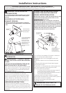
CONNECTING THE DRYER TO HOUSE VENT
RIGID METAL TRANSITION DUCT
• For best drying performance, a rigid metal transition duct is
recommended.
• Rigid metal transitions ducts reduce the risk of crushing and
kinking.
UL-LISTED FLEXIBLE METAL (SEMI-RIGID) TRANSITION DUCT
• If rigid metal duct cannot be used, then UL-listed exible metal
(semi-rigid) ducting can be used (Kit WX08X10077).
• Never install exible metal duct in walls, ceilings, oors or
other enclosed spaces.
• Total length of exible metal duct should not exceed 8 feet
(2.4m).
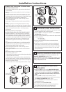
• For many applications, installing elbows at both the dryer
and the wall is highly recommended (see illustrations below).
Elbows allow the dryer to sit close to the wall without kinking
and or crushing the transition duct, maximizing drying
performance.
• Avoid resting the duct on sharp objects.
UL-LISTED FLEXIBLE METAL (FOIL-TYPE) TRANSITION DUCT
• In special installations, it may be necessary to connect the
dryer to the house vent using a exible metal (foil-type) duct.
A UL-listed exible metal (foil-type)duct may be used ONLY
in installations where rigid metal or exible metal (semi-rigid)
ducting cannot be used AND where a 4” diameter can be
maintained throughout the entire length of the transition
duct.
• In Canada and the United States, only the exible metal(foil-
type) ducts that comply with the “Outline for Clothes Dryer
Transition Duct Subject 2158A” shall be used.
• Never install exible metal duct in walls, ceilings, oors or
other enclosed spaces.
• Total length of exible metal duct should not exceed 8 feet
(2.4m).
• Avoid resting the duct on sharp objects.
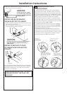
• For best drying performance:
1. Slide one end of the duct over the clothes dryer outlet pipe.
2. Secure the duct with a clamp.
3. With the dryer in its permanent position, extend the duct
to its full length. Allow 2” of duct to overlap the exhaust pipe.
Cut o and remove excess duct. Keep the duct as straight as
possible for maximum airow.
4. Secure the duct to the exhaust pipe with the other clamp.
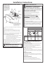
DO
ELBOW HIGHLY
RECOMMENDED
ELBOWS HIGHLY
RECOMMENDED
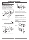
DON’T
DO NOT USE
EXCESSIVE
EXHAUST
LENGTH
DO NOT
CRUSH
FLEXIBLE
EXHAUST
AGAINST
WALL
DO NOT
SIT DRYER
ON FLEXIBLE
EXHAUST
7
BATHROOM OR BEDROOM INSTALLATION
• The dryer MUST be vented to the outdoors. See
EXHAUST INFORMATION section 3 & 4.
• The installation must conform with local codes or, in the
absence of local codes, with the NATIONAL ELECTRICAL
CODE, ANSI/NFPA NO. 70.
8
MOBILE OR MANUFACTURED HOME
INSTALLATION
• Installation MUST conform to the MANUFACTURED HOME
CONSTRUCTION & SAFETY STANDARD, TITLE 24, PART 32-80
or, when such standard is not applicable, with AMERICAN
NATIONAL STANDARD FOR MOBILE HOME, ANSI/NFPA NO.
501B.
• The dryer MUST be vented to the outdoors with the
termination securely fastened to the mobile home structure.
(See EXHAUST INFORMATION section 3 & 4).
• The vent MUST NOT be terminated beneath a mobile or
manufactured home.
• The vent duct material MUST BE METAL.
• Do not use sheet metal screws or other fastening devices
which extend into the interior of the exhaust vent.
• See section 2 for electrical connection information.
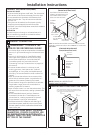
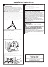
6
ALCOVE OR CLOSET INSTALLATION
• If your dryer is approved for installation in an alcove or closet,
it will be stated on a label on the dryer back.
• The dryer MUST be vented to the outdoors. See the EXHAUST
INFORMATION sections 3 & 4.
• Minimum clearance between dryer cabinet and adjacent walls
or other surfaces is:
0 in. either side
3 in. front and rear
• Minimum vertical space from oor to overhead cabinets,
ceiling, etc. is 52 in.
• Closet doors must be louvered or otherwise ventilated and
must contain a minimum of 60 sq. in. of open area equally
distributed. If the closet contains both a washer and a dryer,
doors must contain a minimum of 120 sq. in. of open area
equally distributed.