


PAGE 4
EXHAUST LENGTH CALCULATION
WHEN INSTALLED IN MANUFACTURED
(MOBILE) HOMES -
USE OF CASTERS
(120V PORTABLE MODELS ONLY)
NOTE TO INSTALLER -
...AFTER INSTALLATION
CHECK THE FOLLOWING
ALCOVE OR CLOSET
INSTALLATION
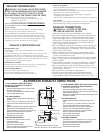
Parts are available from your local service organization:
If your dryer is approved for installation in an alcove or closet, it will be stat-
ed on a label on the dryer back. The installation must conform to the follow-
ing specifications;
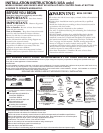
WARNING: TO PREVENT LARGE AMOUNTS OF LINT AND
MOISTURE FROM ACCUMULATING AND TO MAINTAIN DRYER
EFFICIENCY, THIS MACHINE MUST BE EXHAUSTED OUTDOORS.
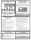
Minimum clearances between dryer cabinet and adjacent walls or other
surfaces are:
NOTE: The clearances stated above are minimums. Consideration
must be given to the type accessory kit used with dryer. Refer to
the specific kit instruction for details.
Sides
Top
Front
Rear
Alcove Closet
0”
1”
-
3”
1”
1”
3“
3”
Closet doors must be louvered or otherwise ventilated and must contain
at least 60 square inches of area equally distributed. If this closet contains
both a washer and a dryer, doors must contain at least 120 square
inches of open area equally distributed.
EXHAUST DUCT - must meet specs on Page 3. No excessive turns.
No kinks or obstructions to air flow.
EXHAUST HOOD - should work freely and open downward.
GROUNDING - Dryer must be properly grounded to conform to local
codes and ordinance requirements.
OPERATION - turn dryer on and check for heat.
HAND CUSTOMER THE USE AND CARE BOOK - Give instructions
on operating the dryer - answer any questions.
GIVE THESE INSTALLATION INSTRUCTIONS to the customer.
Dryer must be exhausted to the outside. Exhaust MUST NOT be terminated
beneath mobile home. Exhaust material MUST NOT support combustion.
Installation MUST conform to Manufactured Home Construction & Safety
Standard, Title 24 CFR, Part 32-80 or when such standard is not applicable, the
American National Standard of Mobile Homes, ANSI/NFRA No. 501B-1977.
For electrical connection, see “Connecting dryer using 4 wire connection”.
For a portable installation screw casters into the holes on the bottom of the dryer. Refer to the “Installation Instructions for
caster assembly” sheet to install casters.
WX8X63 4”X1’ Duct
WX8X64 4”X2’ Duct
WX8X51 Elbow
WX8X59 Aluminum hood
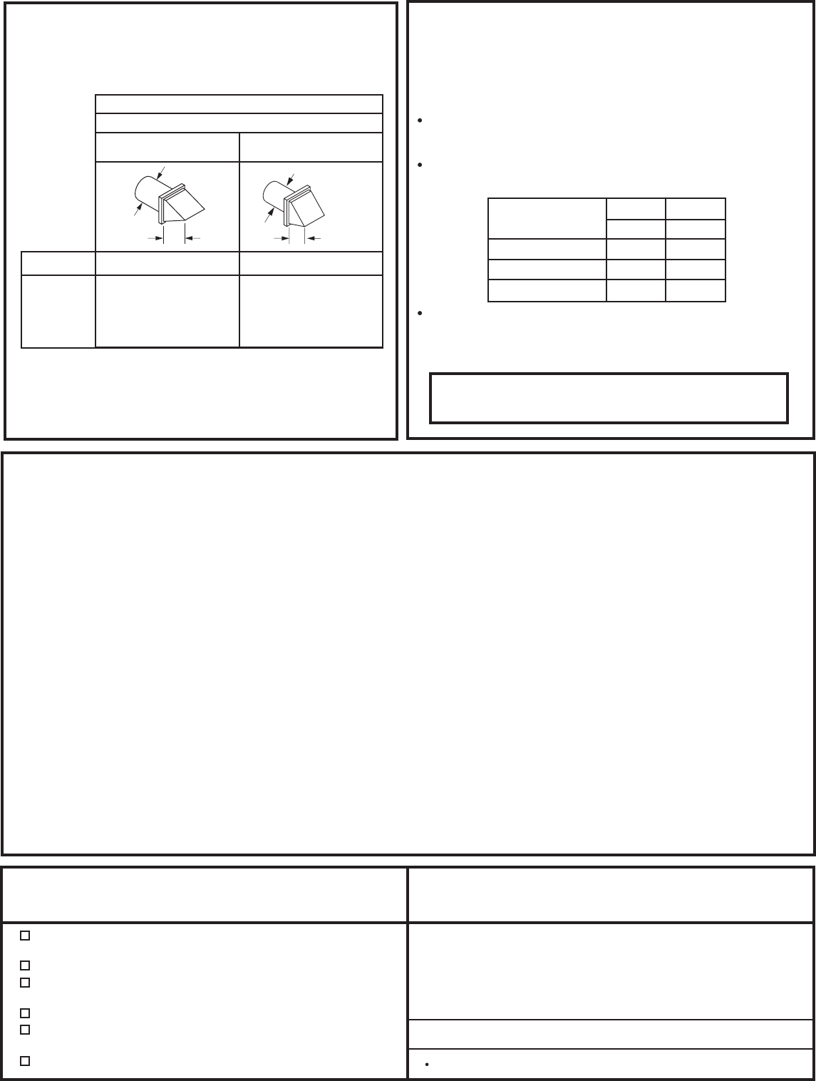
RIGID (Preferred)
FLEXIBLE
4" DIA.
4"
4" DIA.
2-1/2"
RECOMMENDED MAXIMUM LENGTH
Exhaust Hood Types
Recommended
No. of 90º
Elbows
Rigid
Metal
Rigid
Metal
14 m (46 ft)
11 m (38 ft)
9 m (31 ft)
7 m (24 ft)
0
1
2
3
11 m (37 ft)
9 m (30 ft)
6.5 m (22 ft)
4.5 m (15 ft)
Use only for short
run installations
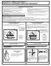
CONNECTING THE DRYER
TO HOUSE VENT
Rigid metal transitions ducts reduce the risk of crush-
ing and kinking.
•
Never install flexible metal duct in walls, ceilings, floors
or other enclosed spaces.
•
•
For best drying performance, a rigid metal transition
duct is recommended.
Avoid resting the duct on sharp objects.
•
In Canada and the United States, only the flexible
metal(foil-type) ducts that comply with the “Outline for
Clothes Dryer Transition Duct Subject 2158A” shall be
used.
•
For many applications, installing elbows at both the
dryer and the wall is highly recommended (see illustra-
tions below). Elbows allow the dryer to sit close to the
wall without kinking and or crushing the transition
duct, maximizing drying performance.
•
Total length of flexible metal duct should not exceed 8
feet (2.4m).
•
RIGID METAL TRANSITION DUCT
•
If rigid metal duct cannot be used, then UL-listed
flexible metal (semi-rigid) ducting can be used (Kit
WX08X10077).
UL-LISTED FLEXIBLE METAL (SEMI-RIGID) TRANSITION DUCT
•
In special installations, it may be necessary to connect
the dryer to the house vent using a flexible metal (foil-
type) duct. A UL-listed flexible metal (foil-type)duct
may be used ONLY in installations where rigid metal or
flexible metal (semi-rigid) ducting cannot be used AND
where a 4" diameter can be maintained throughout the
entire length of the transition duct.
Never install flexible metal duct in walls, ceilings, floors
or other enclosed spaces.
•
Total length of flexible metal duct should not exceed 8
feet (2.4m).
•
Avoid resting the duct on sharp objects.
•
For best drying performance:
•
1. Slide one end of the duct over the clothes dryer outlet pipe.
2. Secure the duct with a clamp.
3. With the dryer in its permanent position, extend the
duct to its full length. Allow 2” of duct to overlap the
exhaust pipe. Cut off and remove excess duct. Keep
the duct as straight as possible for maximum airflow.
4. Secure the duct to the exhaust pipe with the other clamp.
UL-LISTED FLEXIBLE METAL (FOIL-TYPE) TRANSITION DUCT
Total length of flexible metal duct shall not exceed 8 ft (2.4 m).
The following kit is available from you local service organization:
Kit WX08X10077 - 4” dia. flexible metal (semi-rigid) UL-listed
transition duct (includes 2 elbows).
322B3166P001 pub # 31-16233