


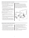

Gas connection
Remove the shipping cap from gas pipe at the rear of the 1.
dryer.
Connect a 1/2 inch (1.27 cm) I.D. semi-rigid or approved 2.
pipe from gas supply line to the 3/8 inch (0.96 cm) pipe
located on the back of the dryer. Use a 1/2 inch to 3/8
inch (1.27 cm to 0.96 cm) reducer for the connection.
Apply an approved thread sealer that is resistant to the
corrosive action of liquefi ed gases on all pipe connections.
Open the shutoff valve in the gas supply line to allow gas 3.
to fl ow through the pipe. Wait a few minutes for gas to
move through the gas line.
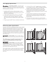
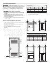
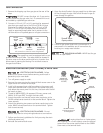
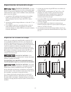
All connections must be wrench-tightened
Flare
Union
Flare
Union
GAS FLOW
Manual
Shuto
Valve
Closed
Open
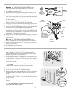
Flexible
Connector
Inlet Pipe on
Back of Dryer
elppiN
Shuto Valve -
Open position
to dryer
from gas supply
Check for gas system leaks with a manometer. If a 4.
manometer is not available, test all connections by
brushing on a soapy water solution.
10
- EXPLOSION HAZARD - NEVER test for gas
leaks with an open fl ame.
The supply line must be equipped with an ap-
proved manual shutoff valve. This valve should be located in
the same room as the dryer and should be in a location that
allows ease of opening and closing. Do not block access to
the gas shutoff valve.
DO NOT connect the dryer to L.P. gas service
without converting the gas valve. An L.P. conversion kit must
be installed by a qualifi ed gas technician.
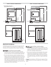
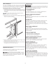
Electrical connection (non-Canada) 3-wire cord
Turn off power supply to outlet. 1.
Remove the screw securing the terminal block access cover in the 2.
upper corner on the back of the dryer.
Install a UL-approved strain relief according to the power cord/3.
strain relief manufacturer’s instructions in the power cord entry
hole below the access panel. At this time, the strain relief should
be loosely in place.
Thread an UNPLUGGED, UL-approved, 30 amp. power cord, 4.
NEMA 10-30 type SRDT, through the strain relief.
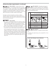
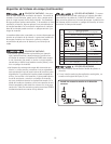
Attach the power cord neutral (center wire) conductor to the 5.
SILVER colored center terminal on the terminal block. Tighten the
screw securely.
Attach the remaining two power cord outer conductors to the 6.
outer, BRASS colored terminals on the terminal block. Tighten
both screws securely.
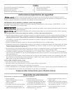
3-wire
receptacle
(NEMA type
10-30R)
Neutral
terminal
Neutral
Neutral
(center wire)
(center wire)
30 AMP
30 AMP
NEMA 10-30
NEMA 10-30
Follow manufacturer’s guidelines for fi rmly securing the strain 7.
relief and power cord.
Reinstall the terminal block cover.8.
- ELECTRICAL SHOCK HAZARD - Failure
to disconnect power source before servicing could result in
personal injury or even death.
- ELECTRICAL SHOCK HAZARD - Do not
make a sharp bend or crimp wiring/conductor at connections.
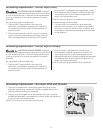
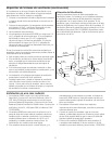
If moving dryer from a 4-wire system
and installing it in a 3-wire system, move the internal
ground from the center terminal back to the GREEN
screw next to the terminal block.
DO NOT remove
internal ground in a
3-wire system!