


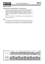

Service
Manual
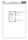
Type
12
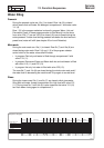
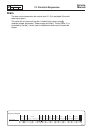
12. Function Sequences
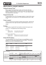
13 9010
PageEdition
3''
(27)''
P1+ 120''
Off/Start
30''
30''
30''
3''
27''
30''
P1+ 120''
30''
30''
30''
30''
30''
30''
P2+ 120''
30''
30''
3''
27''
P2+ 30''
30''
30''
3''
27''
30''
P2+ 30''
30''
30''
3''
27''
30''
30''
P2+ 30''
30''
30''
30''
30''
30''
120''
30''
30''
3''
27''
30''
30''
120''
1
2
34
56
7
89
10
11 12
13 14 15
16
17
18 19
20
21
22
23
24
25
26
27
28 29
30
31
32
33 34
35
36 37
38 39
40 41
42 43 44
45
46
4748 49
50
51 52
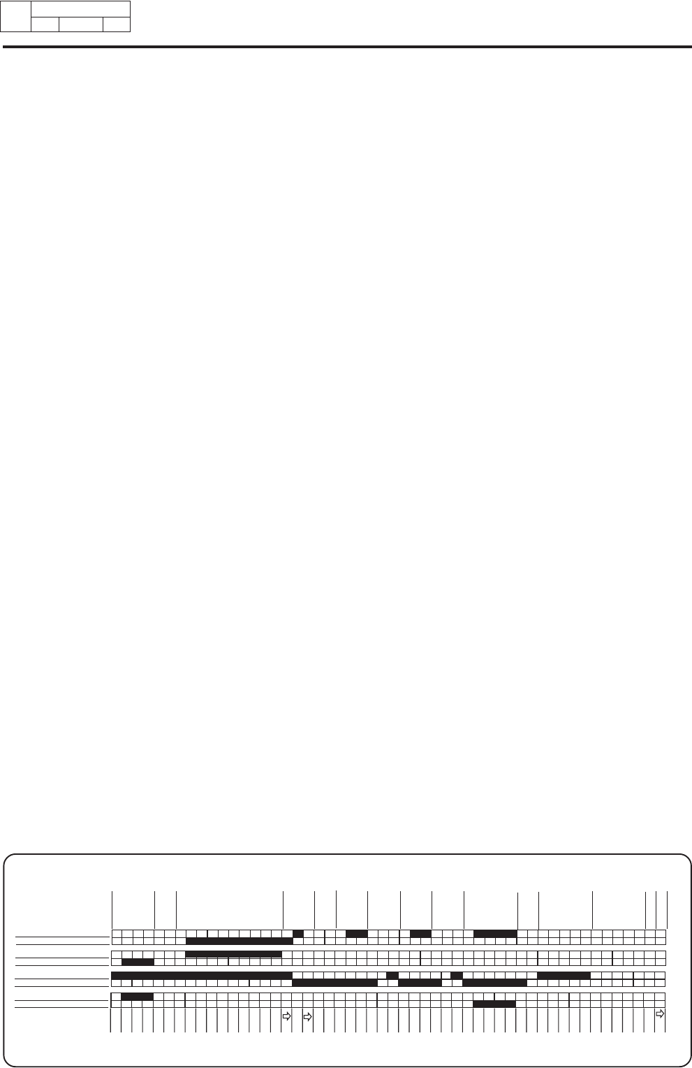
Drain
Mainwash
Cool
down
Rinse 1
Drain/
Spin
Rinse 2
Tumbling
Open
Start
Prewash Drain
Drain/
Spin
Rinse 3
Drain Spin
Water filling
Prewash
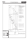
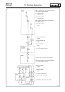
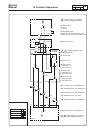
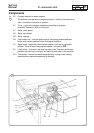
During the prewash cycle row 13a (1) is closed. Row 14a (6) is closed
which means that cold water fills detergent compartment 1 with water valve
Y11 (9).
Row 1 (5) in the program selectros is closed in program Warm, Hot and
Permanent Press. In these programs water is filled directly into the drum
from valve Y24 (17) as row 10b (8) is closed. All rows is closed during the
entire prewash. If water level during prewash falls below the level sensor's
preset level, water will refill (see chapter 26 on Level Detection).
Main wash
During the main wash row 13a (1) is closed. Row 5b (7) and 10a (8) are
closed during main wash. Row 2 (4) and 1 (5) of the program selector
control which of the water valves shall fill water:
• In program Cold only cold water is filled through compartment 2 with
valve Y12 (11).
• In program Permanent Press and Warm both hot and cold water is filled
with valve Y12 (11) and Y22 (13).
• In program Hot only hot water is filled with valve Y22 (13).
The rows 5b (7) and 10a (8) are closed during the whole main wash and if
the water level is decreasing the machine will fill up again to correct level.
Rinse
During the rinses rows 13b (1) and 5a (7) are closed, which gives water
filling with cold water through compartment 2 to high level with valve Y12
(11). During rinse No. 3 row 14b (b) is also closed so that valve Y13 (10)
can flush down rinsing agent in compartment 3.
1566
12
Sequence diagram
5a Inlet valve Y12
5b Inlet valve Y12
10a Inlet valve Y22
10b Inlet valve Y24
13a Level 1
13b Level 2
14aInlet valve Y11
14b Inlet valve Y13