


Service
Manual
Type
12
12 9005
12. Function Sequences
Page
Edition
1557
12
1
2
34
56
7
89
10
11 12
13 14 15
16
17
18 19
20
21
22
23
24
25
26
27
28 29
30
31
32
33 34
35
36 37
38 39
40 41
42 4344
45
46
4748 49
50
51 52
53
54
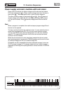
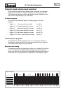
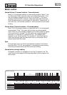
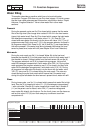
Prerinse
Drain
Mainwash
Cool
down
Rinse 1
Drain/
Spin
Rinse 2
Rinse 4
Tumbling
Open
Start
Prewash
Drain
Drain
Drain/
Spin
Rinse 3
Drain/
Spin
Drain/
Spin
(30'')
30''
P+
L+ 1'
3''
27''
30''
P+ T+
3'
1'
1'
L+ 1'
3''
1'
1'
T+ 1'
P+ 3'
30''
27''
1'
4'
1'
1'
1'
1'
2'
T- 1'
L+ 1'
1'
P+ 1'
30''
30''
L+ 1'
P+ 1'
L+ 1'
30''
P+ 1'
30''
L+ 1'
30''
30''
1'
L+ 1'
1'
3'
3''
L+ 27''
30''
30''
3''
2'
Off/Start
P+ 1'
30 seconds
30 seconds
30 seconds30 seconds30 seconds
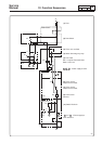
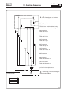
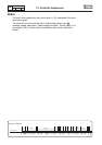
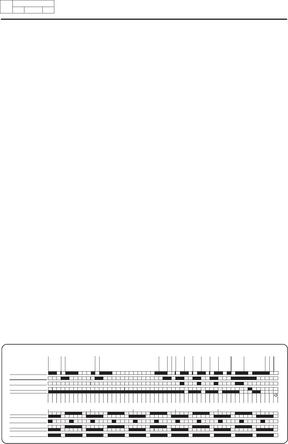
Sequence diagram
14a. Normal action
13b. Spin 1
11a. M21 direct/level 0
9a. M21 direct
21a. Action right
22b. Gentle action
23a. Action right
24b. Normal action
14b. Normal/gentle action
21b. Action left
23b. Action left
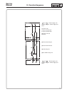
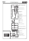
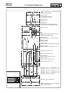
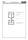
Motor control
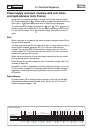
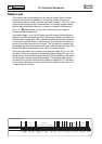
Normal Action (12 second rotation - 3 second pause)
Row 8 (1) in the program selector is closed during programs ”Warm”, ”Hot”
and ”Permanent Press” when the motor is running at normal action. From
row 8 the voltage is supplied via row 14b (5) to row 24b (7). This row is
located in the timer's built-in reverser, where each stage lasts 3 seconds.
Row 24b switches over at normal speed (12 seconds on, 3 seconds off, 12
seconds on etc.) and controls contactor K1 which activates the motor wash
winding.
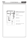
Gentle Action (3 second rotation - 12 second pause)
Row 10 (2) in the program selector is closed and row 8 (1) is de-energised
during program ”Cold”. This means that the motor is running at gentle
action. From row 10 the voltage is supplied via row 22b (3) which is located
in the motor’s built-in reverser. The rows switch over at gentle speed (3
seconds on, 12 seconds off, 3 seconds on etc.). The voltage is then
supplied via row 14b (5) and 24b (7) to contactor K1 which activates the
motor wash winding. Row 24b does switch over at normal action, but is
always closed when 22b closes.
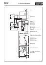
Spin
During the spin cycle, row 13b (6) activates spin contactor K4 (9). At the
same time K4:21 -22 (10) de-energises K1, preventing the wash winding
from being connected at the same time as the spin winding.
Normal action during tumbling
At stage 48, contactor K1 is supplied via row 14a (5) instead of 14b. The
motor runs at normal speed at this stage regardless of which program has
been chosen.