Page -12- CLARKE TECHNOLOGY Operator's Manual -SCRUBTEC 743 and 751
Machine Control Panel
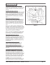
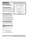
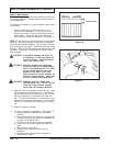
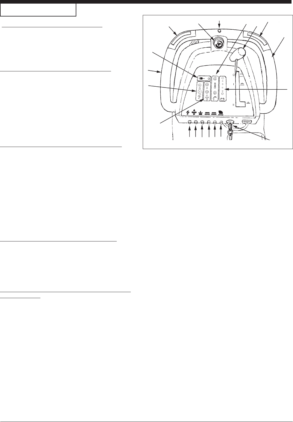
Reverse Switch (See Figure 3, Item "H")
On Traverse "L" Models Only - The reverse switch,
when used in conjunction with one of the forward/
reverse switches, causes the machine to reverse
directions. The reverse speed is 70% of the forward
speed.
Brush Motor Buttons (See Figure 3, Item "I")
To lower brush head and activate brush motor(s) and
solution flow, press and hold the down button until the
green light is illuminated. Continue to press and hold
down button for additional brush pressure, or until brush
head stops. The brush motor(s) and solution will then
operate when either one or both of the forward/reverse
button(s) are pressed. To deactivate the brush motor(s)
and solution flow, raise the brush head by pressing and
holding the up button until the green indicator light turns
off.
Solution Control Buttons (See Figure 3, Item "J")
The solution control buttons regulates the flow of
chemical solution to the floor. When powering up the
machine, the solution setting will automatically adjust to
the mid setting (see your authorized ALTO serviceman if
a different setting is preferred). To increase the flow,
press and hold or press the upper button (+) multiple
times. The green bar will move up the scale as the flow
increases. To decrease the flow, press and hold or
press the lower button (-) multiple times. The green bar
will move down the scale as the flow decreases. When
the bar reaches the lowest setting the solution flow is
turned "OFF". NOTE: The solution will only flow when
the brush head is down and in the operating position.
Vacuum Motor Switch (See Figure 3, Item "K")
To activate the vacuum motor, lower the squeegee
handle. The handle has three positions. Lowest
position is the operating water pickup position. The
center position is used during transport to clear vacuum
hose. The upper position is the vacuum motor "OFF"
position.
Circuit Breakers (Figure 3, Items "L", "M", "N",
"O", "P" & "Q"
The circuit breaker reset buttons are located on the
lower control handle. The breakers are located as
follows:
Item "L" - Control Circuits (5 amps)
Item "M" - Control Module and Head Actuator (5
amps)
Item "N" - Vacuum Motor (25 amps)
Item "O" - Rotary Brush Motor (40 amps) or
Cylindrical Brush Motor (25 amps)
Item "P" - Cylindrical Brush Motor (25 amps)
Item "Q" - Traverse Motor (25 amps) (L Models Only)
Figure 3
A
E
C
I
G
F
H
J
K
G
D
E
B
QP0
N
ML


