


© Copyright, Alliance Laundry Systems LLC – DO NOT COPY or TRANSMIT
Installation
17
AJ1031
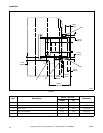
Location Requirements
NOTE: If a forklift is used to move press, exercise
care that forklift arms are inserted under frame
and DO NOT CONTACT ANY OPERATING
MECHANISM.
Moving press to installation location while still
attached to skid is recommended. However, press can
be removed from skid before moving.
Removing Press from Skid
Unscrew four shipping screws from attaching holes.
Using a forklift, lift press and remove skid.
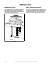
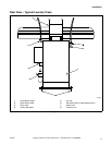
Press should be located in an area that provides a
minimum of 24 inches (61 cm) between press and any
structure.
NOTE: Above dimensions are considered
MINIMUM working and maintenance dimensions
and SHOULD BE INCREASED if possible.
Space between front of table and closest structure
should be determined by work requirements, but in no
case should be less than 30 inches (76.2 cm).
Foundation Requirements
Install press on a solid, level floor such as concrete.
NOTE: Installation on a wooden floor can cause
machine to shift, which WILL result in
MISALIGNMENT of heads and bucks and
DAMAGE to both press and garments.
Floor should be capable of supporting 125 pounds per
square foot (56.7 kg). Remove all floor covering
material (tile, wood, carpeting, etc.) from press
mounting area.
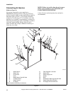
Uncrating
Remove front cover from press and use a hammer to
knock out shipping brace.
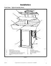
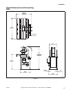
Installing Anchor Bolts and
Levelling Press
After press is in position, attach and level it to floor
with four anchor bolts (obtain locally). Using the
frame base anchor bolt holes as a template, drill four
holes in floor. Holes must be drilled deep enough to
properly install bolts in accordance with
manufacturer’s instructions. Securely tighten anchor
bolts.
Ensure press is level front and back, as well as left and
right. Place a spirit level on top of frame. If press is not
level, raise and lower corners as required. Place
sufficient shims between press frame and floor. Shims
should be sized to make maximum contact with floor
and frame to distribute weight evenly. Use industrial
grout if necessary.
NOTE: Prior to bolting to floor, shim press frame
to eliminate rocking.
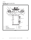
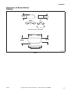
Connecting Steam Supply and
Returns
(Refer to Figure 8)
NOTE: Clean out ALL pipe lines BEFORE
connecting them to press. Failure to properly install
suitable traps and check valves AND supply correct
steam pressure WILL REDUCE operating
efficiency.
Steam supply connected to press must have a constant
pressure of 115 psig (7.9 bar).
The following steps outline the procedure for
connecting steam supply and return lines to press:
1. Run a 1/2 NPT steam supply to steam supply
connection with suitable black iron pipe, elbows,
strainer, ball valve and union.
NOTE: A MINIMUM 3 inch (7.62 cm) riser should
be installed off supply header to minimize water in
steam supply to press.
NOTE: It is recommended that a steam strainer be
installed between steam supply and press.
2. Install two suitable 1/2 NPT unions, steam traps,
check valves and one ball valve between steam
return connections and steam return lines.
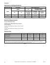
NOTE: Cast iron inverted bucket traps are
recommended. Size traps according to steam
pressure and consumption found in Specifications
in Table 1.
To avoid possible serious injury:
• ALWAYS be careful to AVOID spring-
loaded components when working
inside press.
• Installation MUST be performed ONLY by
qualified service personnel.
W336
WARNING