


23
GB
m odel
LB 6 T - LB 6 TX
dimensions
width cm 59,8
height cm 82
depth cm 53,7
capacity
1 - 5 Kg
electrical
connections
voltage 220/230 Volt 50 Hz
maximum absorbed power 2300 W
water
connections
maximum pressure 1 M Pa (10 bar)
minimum pressure 0,05 MPa (0,5 bar)
drum capacity 42 litres
spinning speed
up to 600 rpm
This appliance conforms with the follow ing E.E.C.
directives:
- 73/23/EEC of 19/02/73 (Low Voltage) and
subsequent modifications
- 89/336/EEC of 03/05/89 (Electrom agnetic
Compatibility) and subsequent modifications
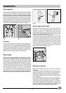
Using the Drilling Template
·
Place the top edge of the drilling template so that it is flush
with the top edge of the panel, making sure that it is positioned
correctly and centered in the horizontal direction (use the dotted
lines on the edges to line the template up). Mark the points on
the panel for the four holes.
· Use an appropriately sized router to mill the holes for the
two hinges, the rubber plug and the magnet.
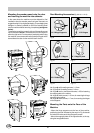
Mounding the Parts onto the Wooden Panel
(Door)
· Insert the hinges into the holes (the movable part of the
hinge must be positioned facing away from the panel) and
fasten them with the 4 type A screws.
· Insert the magnet into the top hole on the opposite side
of the hinges and fasten it with the two type B screws.
· Insert the rubber plug into the bottom hole.
The panel is now ready to be mounted onto the machine.
Mounting the Panel into the machine
Insert the nib of the hinge (indicated by the arrow in fig. 9)
into the hole for the hinge and push the panel towards the
front of the machine. Fasten the two hinges with the type
D screws.
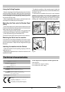
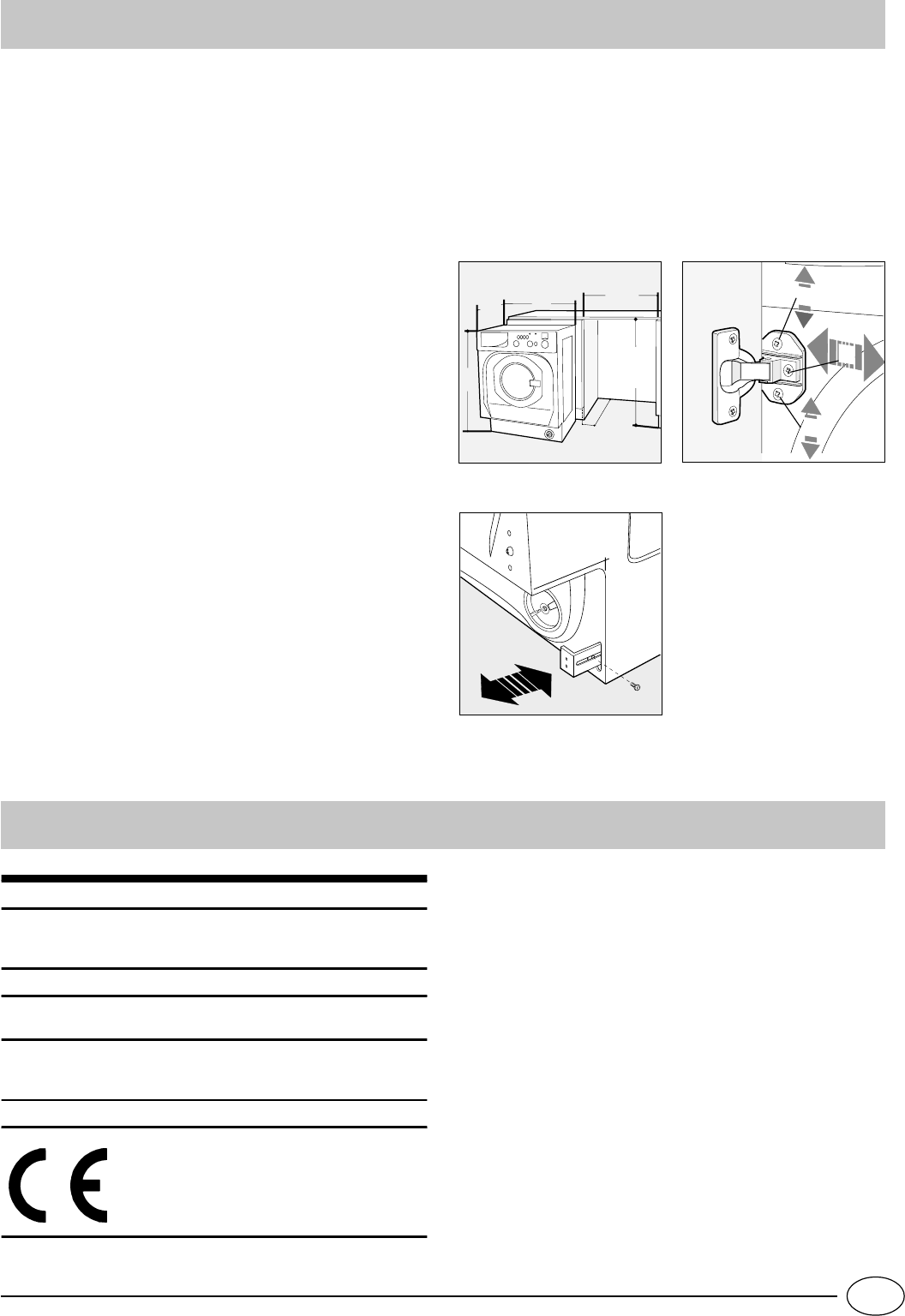
Inserting the machine into the Cabinet
· Push the machine into the opening, aligning it with the
cabinets (fig. 14).
· Regulate the adjustable feet to raise the machine to the
appropriate height.
· To adjust the position of the wooden panel in both the
vertical and horizontal directions, use the C and D screws,
as shown in fig. 15.
· If the machine is installed at the end of a set of modular
cabinets, mount either one or both of the guides for the
base molding (as shown in fig. 16) with the type F screws.
Adjust them for depth based on the position of the base
molding, and, if necessary, fasten the base to the guides.
Technical characteristics
90 mm
570
min
820
537
598
820
÷ 870
600 min
D
C
C
Fig. 16
Fig. 14 Fig. 15
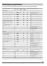
Control programs in compliance with IEC regulation 456:
Cotton program:
Turn knob A to the "program 2"setting;
Turn knob B to the "60°C" setting.