


113403-14 www.amdry.com 15
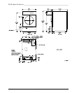
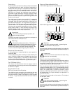
Domestic Type I
(SL20, SL31, SL50 Only)
!
!
!
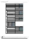
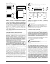
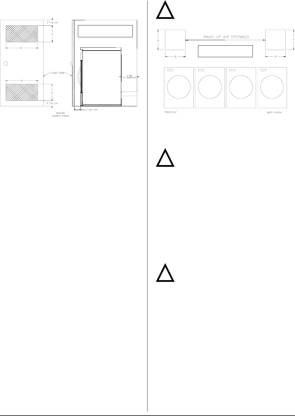
EXAMPLE: For SL50, 2 unrestricted openings measuring
6-inches by 24-inches (15.24 cm by 60.96 cm) are acceptable.
If a closet door is installed: unobstructed air openings are
required. The air openings shall be located 3-inches
(7.62 cm) from the lower opening (above floor level) and upper
opening (below ceiling). The total free area of the air openings
in the door shall not be less than 130 inch
2
(838.708 cm
2
) for
SL20; 179 inch
2
(1154.836 cm
2
) for SL31; and 293 inch
2
(1890.319 cm
2
) for SL50. Louvered doors with equivalent
air openings are acceptable.
No other fuel-burning appliance shall be installed in the same
closet as the dryer.
Fresh Air Supply Requirements ______
When the dryer is operating, it draws in room air, heats it,
passes this air through the tumbler, and exhausts it out of
the building. Therefore, the room air must be continually
replenished from the outdoors. If the make-up air is
inadequate, drying time and drying efficiency will be adversely
affected. Ignition problems and sail switch “fluttering”
problems may result, as well as premature motor failure from
overheating. The dryer must be installed with provisions for
adequate combustion and make-up air supply.
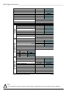
Air supply (make-up air) must be given careful consideration
to ensure proper performance of each dryer. Fresh air
ventilation openings shall not be blocked and/or sealed. As
a general rule, an unrestricted air entrance from the outdoors
of 110 inch
2
(710 cm
2
) is required for each SL75, 90 inch
2
(580 cm
2
) for each SL50, 55 inch
2
(354 cm
2
) for each SL31,
and 40 inch
2
(258 cm
2
) for each SL20. (Based on 1 inch
2
[6.5 cm
2
] per 1,000 Btu [252 kcal].)
It is not necessary to have a separate make-up air opening
for each dryer. Common make-up air openings are
acceptable. However, they must be set up in such a manner
that the make-up air is distributed equally to all the dryers.
To compensate for the use of registers or louvers used over
the openings, this area must be increased by approximately
33%. Make-up air openings should not be located in an area
directly near where exhaust vents exit the building.
Allowances must be made for remote or constricting
passageways or where dryers are located at high altitudes
or predominantly low pressure areas.
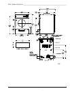
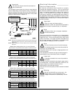
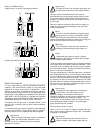
EXAMPLE: For a bank of 4 SL31 dryers, 2 unrestricted
openings measuring 10-inches by 11-inches (25.4 cm by
27.94 cm) are acceptable.
Important
Make-up air must be free of dry cleaning solvent
fumes. Make-up air that is contaminated by dry
cleaning solvent fumes will result in irreparable damage to
the motors and other dryer components.
Exhaust Requirements _______________
Exhaust ductwork should be designed and installed by a
qualified professional. Improperly sized ductwork will create
excessive back pressure, which results in slow drying,
increased use of energy, and shutdown of the burner by the
airflow (sail) switch, burner hi-limits, or lint chamber hi-limit
protector thermostat. The dryer must be installed with a
proper exhaust duct connection to the outside.
The dryer shall not be exhausted into any gas vent, chimney,
wall, ceiling or concealed space of a building.
Caution
This dryer produces combustible lint and must be
exhausted to the outdoors.
Improperly sized or installed exhaust ductwork can create
a potential fire hazard.
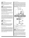
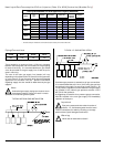
The ductwork should be laid out in such a way that the
ductwork travels as directly as possible to the outdoors with
as few turns as possible. There should be a minimum
6-inch (15.24 cm) clearance between the back guard and
the first bend in the ductwork for ease of servicing. Single or
independent dryer venting is recommended. It is suggested
that the use of 90° turns be avoided; use 30° and/or 45° bends
instead. The radius of the elbows should preferably be
1-1/2 times the diameter of the duct. All ductwork should be
smooth inside with no projections from sheet metal screws
or other obstructions, which will collect lint. When adding
ducts, overlap the duct being connected. All ductwork joints
must be taped to prevent moisture and lint from escaping
into the building. Back draft dampers must be installed in all
commonly ducted systems. Inspection doors should be
installed at strategic points in the exhaust ductwork for
periodic inspection and cleaning of lint from the ductwork.
Note
Component failure due to dry cleaning solvent
fumes will void the warranty.
A = 6-inches (15.24 cm)
B = 24-inches (60.96 cm)
A = 10-inches (25.4 cm)
B = 11-inches (27.94 cm)