


24 American Dryer Corp. 113431-10
!
!
!
!
!
!
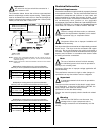
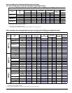
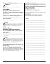
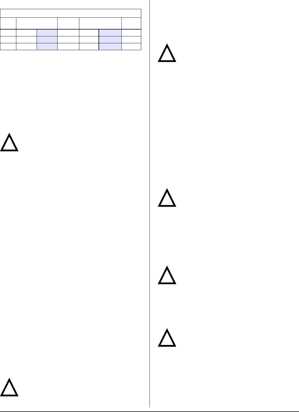
Steam Requirements – High Pressure
Shaded areas are stated in metric equivalents
* The minimum operating pressure for optimum results is 100 psig (689.47
kPa).
Installation Instructions
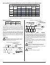
To ensure an adequate supply of steam is provided, be sure
that the steam supply lines and steam return lines are sized
and laid out as stipulated in this manual. Inadequate steam
supply lines and steam return lines or improper steam
plumbing will result in poor performance and can cause
component failure. Clean, dry steam must be provided to the
dryer.
Important
Steam coil failure due to water hammer by wet
steam will void the warranty.
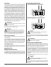
The presence of condensate in the steam supply line will
cause water hammer and subsequent heat exchanger
(steam coil) failure. The steam supply connection into the
main supply line must be made with a minimum 10-inch
(25.4 cm) riser. This will prevent any condensate from draining
towards the dryer.
The steam supply line to the dryer must include a 12-inch
(30.48 cm) riser along with a drip trap and check valve. This
will prevent any condensate from entering the steam coil.
Flexible hoses or couplings must be used. The dryer vibrates
slightly when it runs and this will cause the steam coil
connections to crack if they are hard piped to the supply and
return mains.
Shutoff valves for each dryer should be installed in the supply
line, return line, and drip trap return line. This will allow the
dryer to be isolated from the supply main and the return main
if the dryer needs maintenance work.
Install an inverted bucket steam trap and check valve at least
12-inches (30.48 cm) below the steam coil as close to the
coil as possible. A trap with a minimum capacity of 100 lb
(45.35 kg) of condensate per hour at 125 psi (8.62 bar) is
needed for each unit. (Based on 2 times the steam
consumption per hour.)
The supply line and the return line should be insulated. This
will save energy and provide for the safety of the operator and
maintenance personnel.
Water pockets in the supply line, caused by low points, will
provide wet steam to the coil possibly causing steam coil
damage. All horizontal runs of steam supply piping should
be pitched 1/4-inch (6.35 mm) for every 1 foot (0.31 meters)
back towards the steam supply header causing the
condensate in the line to drain to the header. Install a bypass
trap in any low point to eliminate wet steam.
Important
Flexible hoses/couplings must be used. Coil
failure due to hard plumbing connections will void
the warranty.
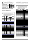
Operating Steam Pressure
Model Maximum
Heat Input
(Normal Load)
Consumption (Approx.)
@ 125 psi (8.6 bar)
Inlet /
Return
M31SL
150 psig*
1.0 MPa
1.75
Bhp 63 lb/hr
28.58 kg/hr
1/2” / 1/2”
M50SL
150 psig*
1.0 MPa
3.75 Bhp 127.5 lb/hr
57.83 kg/hr
3/4” / 3/4”
M75SL
150 psig*
1.0 MPa
4 Bhp 136 lb/hr
61.69 kg/hr
3/4” / 3/4”
Water Information _____________________
Before You Start
Check Local Codes and Permits
Call your local water company or the proper municipal
authority for information regarding local codes.
Important
It is your responsibility to have all plumbing
connections made by a qualified professional to
ensure that the plumbing installation is adequate and
conforms to local, state, and federal regulations or codes.
It is the installer’s or owner’s responsibility to see that the
required water pressure, pipe size, or connections are
provided. The manufacturer assumes no responsibility if
the fire suppression system is not connected, installed, or
maintained properly.
Installation
Water Supply
The fire suppression system must be supplied with a
minimum water pipe size of 1/2-inch (12.7 mm) and be
provided with 40 psi +/- 20 psi (2.75 bar +/- 1.37 bar) of
pressure.
If the rear area of the dryer or the water supply is located in an
area where it will be exposed to cold/freezing temperatures,
provisions must be made to protect these water lines from
freezing.
Warning
If the water in the supply line or water solenoid
valve freezes, the fire suppression system will be
inoperative!!
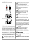
Water Connections
The water connection is made to the 3/4”-11.5 NH hose
adaptor, which is shipped in the tumbler and must be installed
to the 1/2” N.P.T. water connection, located at the upper rear
of the dryer. A flexible supply line/coupling must be used in
an effort to avoid damaging the electric water solenoid valve.
Note
The 3/4”-11.5 NH is a standard hose coupling
screw thread. It is not to be confused with 3/4”
N.P.T. The sealing of an NH connection is made with a
washer opposed to the mating threads of an N.P.T.
assembly. The 2 thread designs are not compatible.
It is recommended that a filter or strainer be installed in the
water supply line.
Important
Flexible supply line/coupling must be used.
Solenoid valve failure due to hard plumbing
connections will void warranty.
The dryer is to be connected to the water mains using a
new hose set and the old hose set should not be reused.