


113615-1 www.amdry.com 11
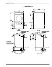
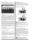
NOTE 1 Opening from combustible materials must be 2-inches (5.08 cm)
larger than the duct (all the way around). The duct must be centered
within this opening.
NOTE 2 Distance should be 2 times the diameter of the duct to the nearest
obstruction.
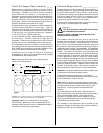
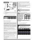
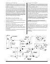
Multiple Dryer Venting with 8-Inch (20.32 cm) Diameter
640 cfm (18.12 cmm) Exhaust Connections at Common Duct
Electrical Information ________________
Electrical Requirements
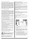
All electrical connections must be made by a properly licensed
and competent electrician. This is to ensure that the electrical
installation is adequate and conforms to local, state, and
national regulations or codes of the country of origin. In the
absence of such codes, all electrical connections, materials,
and workmanship must conform to the applicable
requirements of the National Electrical Code ANSI/NFPA NO.
70-LATEST EDITION or in Canada, the Canadian Electrical
Codes Parts 1 & 2 CSA C22.1-1990 or LATEST EDITION.
Important: Failure to comply with these codes or
ordinances, and/or the requirements stipulated in this
manual can result in personal injury or component failure.
Note: Component failure due to improper installation will
void the warranty.
Each dryer should be connected to an independently
protected branch circuit. The dryer must be connected with
copper wire only. Do not use aluminum wire, which could
cause a fire hazard. The copper conductor wire/cable must
be of proper ampacity and insulation in accordance with
electric codes for making all service connections.
Note: The use of aluminum wire will void the warranty.
An individual ground circuit must be provided to each
dryer, do not daisy chain.
Component failure due to improper voltage application will
void the warranty.
A = 8-inch (20.32 cm)
B =12 feet (3.656 meters)
!
The manufacturer reserves the right to make changes in
specifications at any time without notice or obligation.
Important: A separate protected circuit must be provided
to each dryer.
The dryer must be connected to the electric supply shown
on the data label. In the case of 208 VAC or 240 VAC, the
supply voltage must match the electric service
specifications of the data label exactly.
The wire size must be properly sized to handle the related
current.
Warning
208 VAC and 240 VAC are not the same. Any
damage done to dryer components due to
improper voltage connections will automatically void
the warranty.
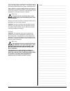
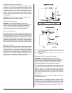
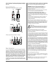
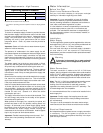
Warning (Gas Models Only)
Dryers built for use with a voltage between 200
and 240 must verify the input voltage during
!
TERM
LINE VOLTAGE
50 Hz 60 Hz
HIGH
260
226
283
249
MED
239
208
260
230
LOW
217
189
236
208
installation. If the nominal
voltage is outside of the
medium tolerances shown
on the diagram below,
adjust the autotransformer,
located near the burner
assembly. To adjust the
autotransformer wiring,
place the red wire on the
appropriate tap (HIGH,
MED, LOW) of the
autotransformer. For additional wiring details, refer to
the electrical diagram located on the inside of the
control panel.
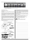
Electrical Service Specifications
Gas and Steam Models Only
7/10/08
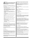
NUMBER OF DRYERS 4 3 2 1
MINIMUM CROSS-
SECTIONAL AREA
SQ IN 164 120 80 54
SQ CM 1058 774.2 516.1 348.4
MINIMUM ROUND
DUCT DIAMETER
IN 14 12 10 8
CM 35.56 30.48 25.4 20.32
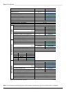
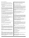
ELECTRICAL SERVICE SPECIFICATIONS
IMPORTANT:
NOTES
: A.
B.
C.
208 VAC AND 230/240 VAC ARE NOT THE SAME. When ordering, specify exact voltage.
When fuses are used they must be dual element, time delay, current limiting, class RK1 or
RK5 ONLY. Calculate/determine correct fuse value, by applying either local and/or National
Electrical Codes to listed appliance amp draw data.
Circuit breakers are thermal-magnetic (industrial) motor curve type ONLY. For others,
calculate/verify correct breaker size according to appliance amp draw rating and type
of breaker used.
Circuit breakers for 3-phase (3ø) dryers must be 3-pole type.
SERVICE
VOLTAGE
PHASE
WIRE
SERVICE
APPROX. AMP DRAW
CIRCUIT
BREAKER
60 Hz 50 Hz
Gas
120 1ø 2 25.5 — 35
208 1ø 2 19.8 — 25
220 1ø 2 14.2 12.3 20
230 1ø 2 — 12.2 20
240 1ø 2 13.4 — 20
Steam
120 1ø 2 22.2 — 30
200 1ø 2 12.0 — 20
208 1ø 2 12.0 — 20
220 1ø 2 12.0 9.6 20
230 1ø 2 — 10.0 20
240 1ø 2 11.3 — 20