


450262-1 www.amdry.com 5
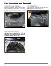
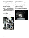
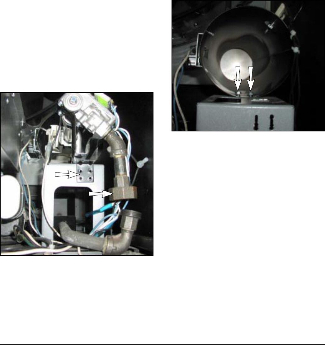
GAS VALVE/IGNITION SYSTEM REMOVAL:
Be sure to shut off the gas main and then proceed
to remove electrical connections and screws
indicated. Remove lower front panel. Disconnect
union and screws noted with arrows.
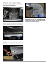
The gas valve and burner orifice can now be carefully
pulled toward the front of the dryer.
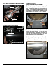
Be sure to pull the assembly straight back so as not
to strike the very fragile carbon ignitor. With the
assembly partly out of the oven, the ignitor and the
two gas valve electrical connections can be
disconnected. At this point the assembly can be
removed from the dryer.
Replace assembly in the reverse order but make
sure the tab at the rear of the assembly engages
into the oven base slot.
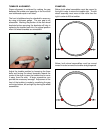
Inspect all wires to be sure all lead directly toward
the front of the dryer. Be sure no wires are caught
on the burner tube or ignitor.
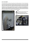
OVEN CHAMBER REMOVAL:
The oven chamber can be removed after the gas
valve/ignition system has been removed.
Remove the two screws indicated by the arrows.
Pull the oven housing part way out through the front
and disconnect all wire connections. The oven
housing can now be removed.
Replace assembly by leading the housing cone into
the hole in the rear wall. Replace screws and wire
connections.