


13
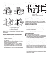
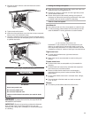
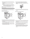
Level Dryer
Check the levelness of the dryer. Check levelness rst side to
side, then front to back.
If the dryer is not level, prop up the dryer using a wood block.
Use a wrench to adjust the legs up or down and check again
for levelness.
NOTE: It might be necessary to level the dryer again after it is
moved into its nal position.
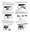
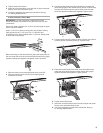
Connect Vent
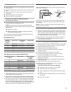
1. Using a 4" (102 mm) clamp, connect vent to exhaust outlet
in dryer. If connecting to existing vent, make sure the vent is
clean. The dryer vent must t over the dryer exhaust outlet
and inside the exhaust hood. Check that the vent is secured
to exhaust hood with a 4" (102 mm) clamp.
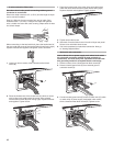
2. Move dryer into its nal location. Do not crush or kink vent.
3. Once the exhaust vent connection is made, remove the
corner posts and cardboard.
Complete Installation
1. Check that all parts are now installed. If there is an extra part,
go back through the steps to see which step was skipped.
2. Check that you have all of your tools.
3. Dispose of/recycle all packaging materials.
4. Check the dryer’s nal location. Be sure the vent is not
crushed or kinked.
5. Check that the dryer is level. See “Level Dryer.”
6. For power supply cord installation, plug into an outlet.
For direct wire installation, turn on power.
7. Remove the protective lm on the console and any tape
remaining on the dryer.
8. Wipe the dryer drum interior thoroughly with a damp cloth
to remove any dust.
9. Read “Dryer Use” in the Dryer User Instructions.
10. Set the dryer on a full heat cycle (not an air cycle) for
20 minutes and start the dryer.
If the dryer will not start, check the following:
Controls are set in a running or “On” position. ■
Start button has been pushed rmly. ■
Dryer is plugged into an outlet and/or electrical supply ■
is on.
Household fuse is intact and tight, or circuit breaker has ■
not tripped.
Dryer door is closed. ■
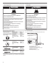
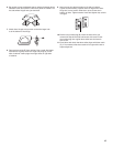
Determine vent path:
Select the route that will provide straightest and most direct ■
path outdoors.
Plan the installation to use the fewest number of elbows and ■
turns.
When using elbows or making turns, allow as much room ■
as possible.
Bend vent gradually to avoid kinking. ■
Use as few 90° turns as possible. ■
Determine vent length and elbows needed for
best drying performance:
Use following Vent system chart to determine the elbow and ■
hood combinations acceptable to use.
NOTE: Do not use vent runs longer than those specied
in the Vent System Chart. Exhaust systems longer than those
specied will:
Shorten life of dryer. ■
Reduce performance, resulting in longer drying times ■
and increased energy usage.
The Vent system chart provides venting requirements that will
help achieve best drying performance.
Vent System Chart
Number
90° turns or
elbows
Type of vent Box/louvered
hoods
Angled hods
0 Rigid metal 64 ft. (20 m) 58 ft. (17.7 m)
1 Rigid metal 54 ft. (16.5 m) 48 ft. (14.6 m)
2 Rigid metal 44 ft. (13.4 m) 38 ft. (11.6 m)
3 Rigid metal 35 ft. (10.7 m) 29 ft. (8.8 m)
4 Rigid metal 27 ft. (8.2 m) 21 ft. (6.4 m)
Vent System Chart (Long Vent Models Only)
Number 90° turns
or elbows
Type of vent Box, louvered,
or angled
hoods
0 Rigid metal 120 ft. (36.6 m)
1 Rigid metal 110 ft. (33.5 m)
2 Rigid metal 100 ft. (30.5 m)
3 Rigid metal 90 ft. (27.4 m)
4 Rigid metal 80 ft. (24.4 m)
5 Rigid metal 70 ft. (21.3 m)
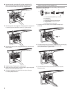
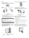
Install Vent System
1. Install exhaust hood. Use caulking compound to seal exterior
wall opening around exhaust hood.
2. Connect vent to exhaust hood. Vent must t inside exhaust
hood. Secure vent to exhaust hood with 4" (102 mm) clamp.
3. Run vent to dryer location. Use the straightest path possible.
See “Determine vent path” in “Plan Vent System.” Avoid 90º
turns. Use clamps to seal all joints. Do not use duct tape,
screws, or other fastening devices that extend into the interior
of the vent to secure vent, because they can catch lint.