Page -8- CLARKE TECHNOLOGY
Operator's Manual -
SCRUBTEC R Manual SteeringSCRUBTEC R Manual Steering
SCRUBTEC R Manual SteeringSCRUBTEC R Manual Steering
SCRUBTEC R Manual Steering
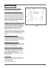
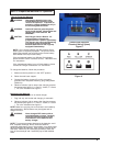
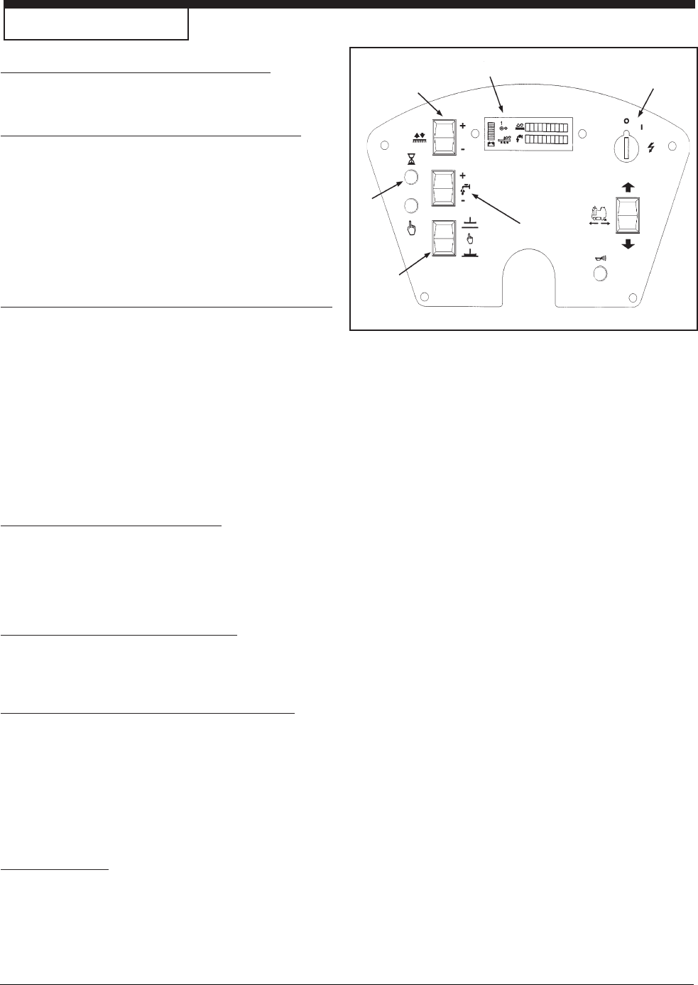
On/Off Key Switch (See figure 1, Item D)
The key switch turns “ON” the power to the control
panel. “O” is the “OFF” and “I” is the “ON”.
Brush Up/Down Switch (See figure 1, Item A)
To lower brush head, push the brush switch in the
down (+) position. To lower the brush head to maxi-
mum brush pressure, continue to hold the switch in
the down (+) position until the travel stops. The brush
motors will start and solution will flow (provided the
solution is turned “ON”) when the machine begins to
traverse. To raise the brush head, push the brush
switch in the up (-) position until the brush head travel
stops or desired position is reached.
Squeegee Up/Down Switch (See figure 1, Item B)
The squeegee switch is used to raise and lower the
squeegee and to turn on and off the vacuum motor.
The vacuum motor is turned on when the switch is
placed in the middle or lower position. NOTE: When
the squeegee switch is placed in the lower
position, the vacuum motor will turn on.
To raise the squeegee, place the switch in either the
middle or up position. The middle position is used for
one touch control. The vacuum motor will stop, after a
short delay, when the switch is placed in the up
position.
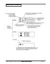
Hour Meter (See figure 1, Item E)
The hour meter is located on the front display. You
must toggle screens using LCD display button. The
hour meter indicates the number of hours the machine
has operated. It displays brush motor, vacuum motor,
traverse motor and total key on times.
Battery Meter (See figure 1, Item F)
The battery meter indicates the relative charge on the
battery pack. The battery meter is located on screen
1 on the front display. See page 7.
Solution Flow Control (See figure 1, Item C)
The solution flow switch regulates the flow of chemical
solution to the floor. To increase the flow, toggle (+).
To decrease the flow, toggle (-). To shut off the
solution, toggle - until no indicators are visible on
display. NOTE: DO NOT run dry!
NOTE: No solution will flow when the machine
does not traverse.
Circuit Breakers
The circuit breaker reset buttons are located on the
back side of the front cover below front display. The
breakers are as follows:
Item A - Main (5 amp)
Item B - Key Switch (5 amp)
Machine Control Panel
Figure 1
A
B
C
D
E
E, F


