44
5
Steam connection
Machines with steam heating must have a steam valve between the steam
installation and the machine.
WARNING
Never touch internal or external steam pipes, connections,
or components. These surfaces can be extremely hot and
will cause severe burns. The steam must be turned off and
the pipe, connections, and components allowed to cool
before the pipe can be touched.
Steam Supply Information
MODEL
Steam inlet
connection, inch
Number of
steam inlets
Recommended
pressure, bar
Recommended
pressure, psi
Maximum
pressure, bar
Maximum
pressure, psi
For the WF150 = WF150, IWF150, IWF033, CWF033 3/8 1 2.0 - 5.5 30 - 80 5.5 80
For the WF185 = WF185, IWF185, IWF040, CWF185, CWF040 3/8 1 2.0 - 5.5 30 - 80 5.5 80
For the WF235 = WF235, IWF235, IWF055, CWF235, CWF055 1/2 1 2.0 - 5.5 30 - 80 5.5 80
For the WF305 = WF305, IWF305, IWF075, CWF305, CWF075 1/2 1 2.0 - 5.5 30 - 80 5.5 80
For the WF400 = WF400, IWF400, IWF090 1/2 1 2.0 - 5.5 30 - 80 5.5 80
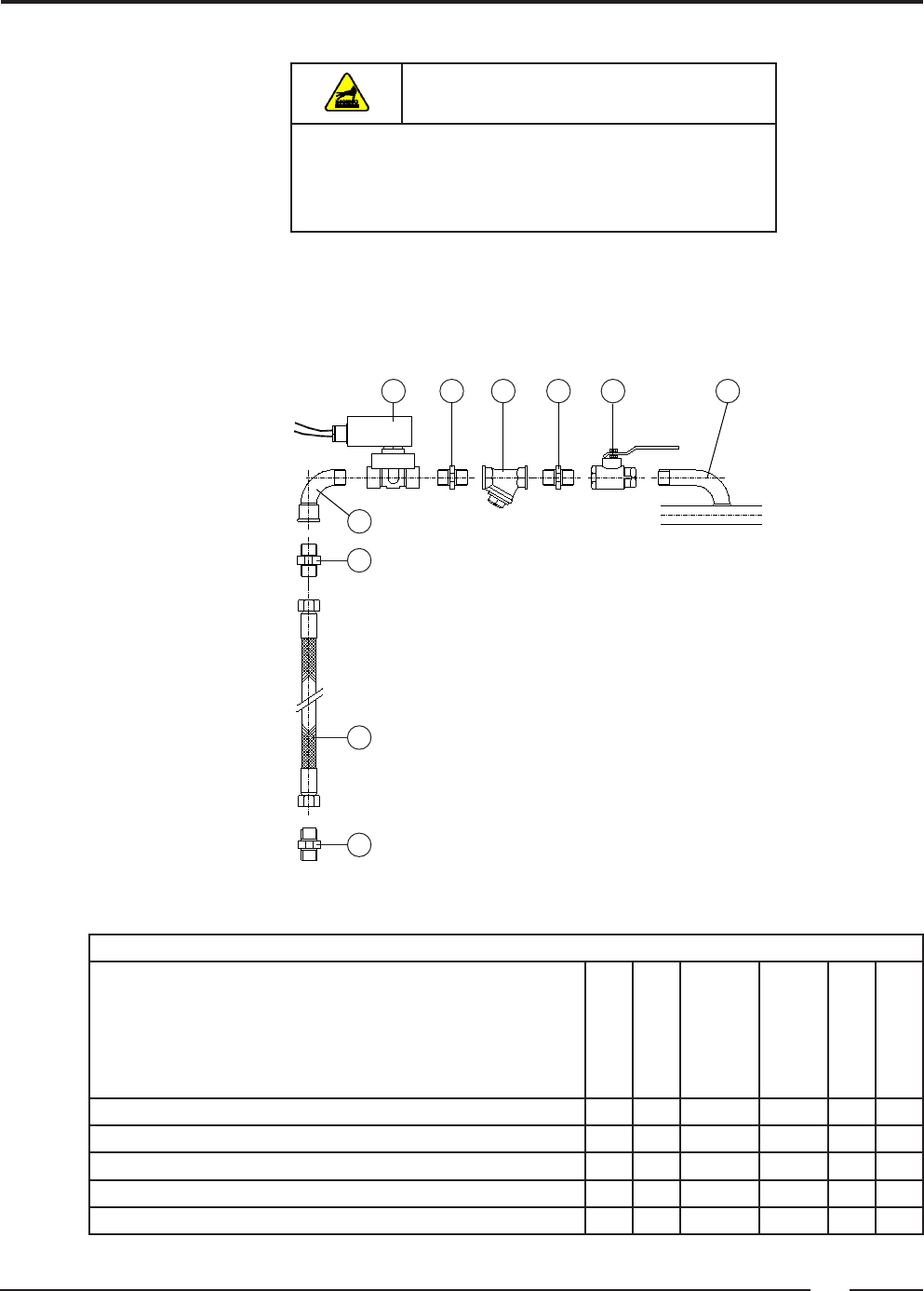
With direct steam injection into the machine (See Table 8)
1. Steam pipe
2. Steam cut-off valve
3. Pipe coupling
4. Steam lter
5. Magnetic steam valve
6. Curve MF
7. Steam hose with appropriate pipe coupling
2345 3 1
6
7
7
7
Table 8


