


© Copyright, Alliance Laundry Systems LLC – DO NOT COPY or TRANSMIT
9
9002062 (EN)
Installation/Operation Supplement
Installation
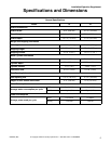
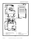
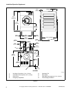
Dimensional Clearances
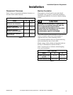
Table 1 shows recommended minimum clearances on
all sides of the washer-extractor.
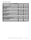
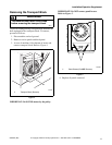
Machine Foundation
Thoroughness of detail must be stressed with all
foundation work to ensure a stable unit installation,
eliminating possibilities of excessive vibration during
extract.
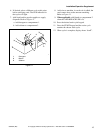
The washer-extractor must be placed on a smooth level
surface so that the entire base of the machine is
supported and rests on the mounting surface.
The standard installation does not require anchoring
unless mandated by state or local codes.
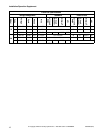
Kinetic energy of the cylinder and dynamic loads on
the floor or foundation are shown in Table 2.
Table 2 can be used as a reference when designing
floors and foundations.
Recommended Minimum Clearances
Model 18 30
Minimum rear clearance
24 in.
(600 mm)
24 in.
(600 mm)
Minimum clearance
between machine and wall
6 in.
(150 mm)
6 in.
(150 mm)
Minimum clearance
between machines (side)
1 in.
(25.4 mm)
1 in.
(25.4 mm)
Minimum front clearance
(door swing)
16.5 in.
(419 mm)
16.5 in.
(419 mm)
Table 1
Floor Load Data
Model 18 30
Kinetic energy of the
cylinder
1386 N/m 2592 N/m
Dynamic bottom load
700 N/16 Hz 1000 N/16 Hz
Table 2
Ensure that the machine is installed on a
level floor of sufficient strength and that
the recommended clearances for
inspection and maintenance are provided.
Never allow the inspection and
maintenance space to be blocked.
W488
CAUTION