


© Published by permission of the copyright owner – DO NOT COPY or TRANSMIT
Installation/Operation Supplement
70278501 (EN)
14
Fire Suppression System
Water Requirements
IMPORTANT: Water must be supplied to the fire
suppression system, or the fire suppression system
will not operate as intended.
Connection point to the electric water solenoid valve is
a 19 mm (3/4 inch) hose. The fire suppression system
equipped tumbler must be supplied with a minimum
water pipe size of 12.7 mm (1/2 inch)and be provided
with a
minimum of 138 kPa (20 psi) and a maximum
of 827 kPa (120 psi) of pressure at all times. Flowrate
must be no less than, but approximately 57 liter
(15 gallons) per minute.
NOTE: Water pressure under 138 kPa (20 psi) will
cause low flow and water leakage at water solenoid
valve.
IMPORTANT: Temperature of the water supply
must be kept between 4.4° and 48.9°C (40° and
120°F). If water in the supply line or water solenoid
valve freezes, the fire suppression system will not
operate.
IMPORTANT: If temperature sensors inside the
tumbler register a temperature below 4.4°C (40°F),
the fire suppression system control will lock out.
This feature protects against operation of the
tumbler with a possible frozen water supply. Only
when the temperature sensors register a
temperature above 4.4°C (40°F) will the machine
reset for operation.
IMPORTANT: Flexible supply line/coupling must
be used. Solenoid valve failure due to hard
plumbing connections will void the warranty. It is
recommended that a filter or strainer be installed
in the water supply line.
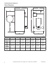
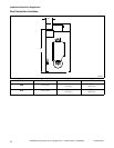
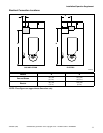
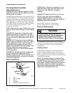
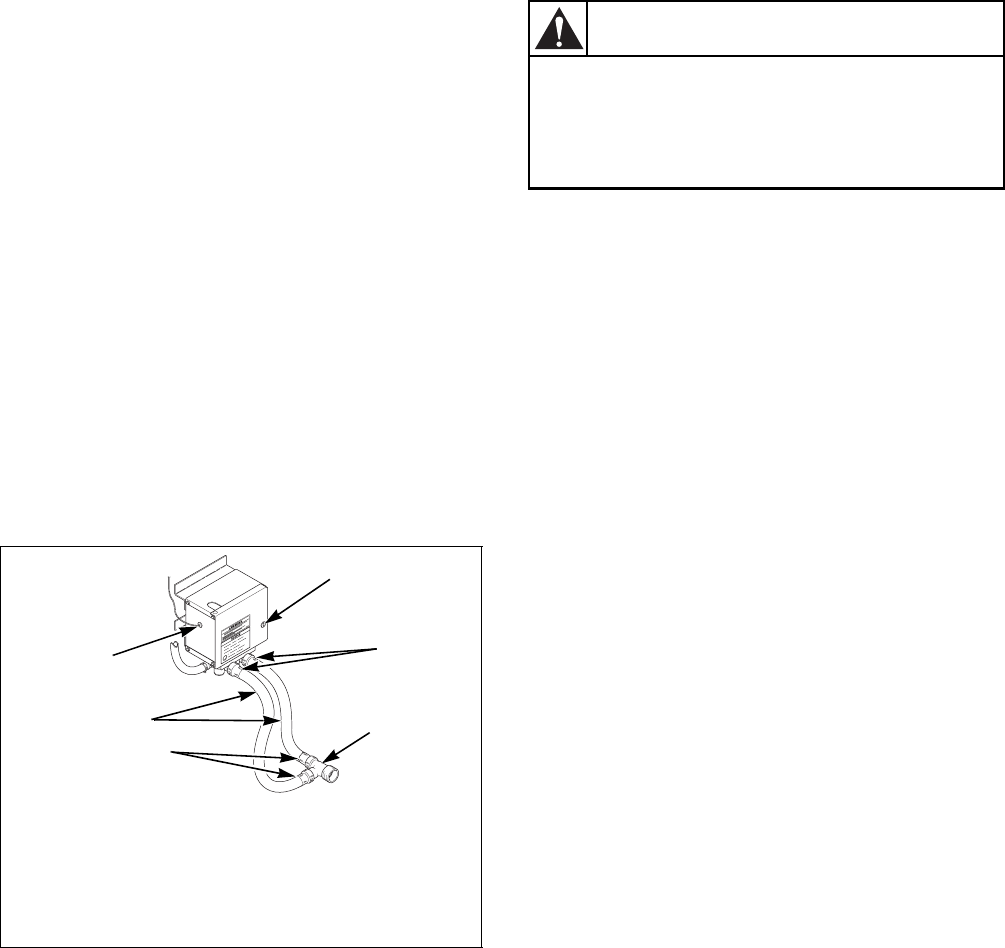
Water Connections
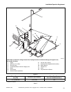
Figure 2
IMPORTANT: Thread hose couplings onto valve
connections finger tight, then turn 1/4 turn with
pliers. Do not cross thread or overtighten
couplings.
IMPORTANT: Replace all hoses every five years.
NOTE: Longer inlet hoses are available (as
optional equipment at extra cost) if the hoses
supplied with the tumbler are not long enough for
installation. Order hoses as follows:
Part No. 20617 Inlet hose 2.44 m (8 feet)
Part No. 20618 Inlet hose 3.05 m (10 feet)
Electrical Requirements
No independent external power source or supply
connection is necessary. Power to operate the 24 Volt
fire suppression system is from the rear junction/
contactor box.
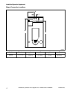
Auxiliary Alarm
During tumbler installation, you have the option to
connect a separate alarm system to this auxiliary
output. Use of the auxiliary output is not required for
the fire suppression system to operate, but may be used
for additional protection.
NOTE: The auxiliary output is activated during
fire suppression system maintenance test sequence.
Consider this fact prior to your system test every
three months. (Example: If the external system uses
the auxiliary output to call the fire department,
inform the fire department before and after the fire
suppression system maintenance test.)
TMB2008N
1 Lock
2 Hose Couplings
3 Y Valve
4 Inlet Hoses
5 Opening for Auxiliary Alarm Cable
1
2
3
2
4
5
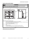
Electrical power must be provided to
tumbler at all times. The fire suppression
system will be inoperative if the main
electrical power supply is disconnected.
W690
WARNING