


Operating Instructions
70400001
20
© Copyright, Alliance Laundry Systems LLC – DO NOT COPY or TRANSMIT
System Tests
The following system tests are performed during
normal operation. System tests are performed at a
minimum of every 24 hours.
Low Voltage Detection
If the voltage between terminals TH and GND on the
control is below 18.75VAC +/- 0.75VAC for more than
3 seconds the ignition control will turn off the gas
valve and will not attempt to spark. The Diagnostic
LED will display Error Code 5. The ignition control
will not enter Lockout Mode if a low voltage condition
is detected, but will enter Standby Mode and wait for
the low voltage condition to be cleared.
If the voltage between terminals TH and GND on the
control rises above 19.75VAC +/- 0.1VAC for at least 3
seconds, the ignition control will then enter Start Up
Mode.
Low Voltage Detection test is disabled during Run
Mode.
Gas Valve
The ignition control verifies that the gas valve is
connected. Failure of this test results in the ignition
control entering Lockout Mode with the Diagnostic
LED displaying Error Code 2.
Flame Probe Tests
Unexpected Presence of Flame
The Unexpected Presence of Flame test is performed
when no flame is expected. Failure of this test results
in the ignition control entering Lockout Mode with the
Diagnostic LED displaying Error Code 3.
Flame Monitoring
During the Flame Monitoring test, the flame is
checked to ensure the gas is being burned when the gas
valve is on. Failure of this test will result in the
ignition control entering Lockout Mode with the
Diagnostic LED displaying Error Code 3.
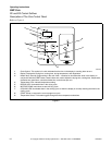
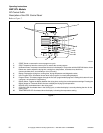
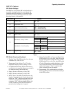
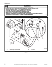
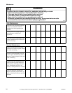
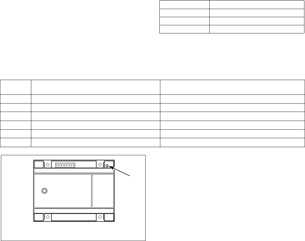
Diagnostic LED (DGN LED) / Error Codes
The Diagnostic LED or DGN LED is located by the
power connector on the ignition control. Refer to
Figure 8. The Diagnostic LED will indicate the status
of the ignition control. Refer to Table 3.
The Diagnostic LED will flash error codes one half
second on and one half second off. Error codes are
separated by a one second pause before the code is
repeated.
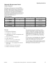
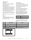
LED Color Description
Orange-Yellow Initialization
Green Standby / Normal Operation
Red Fault Indication Code
Table 3
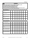
Error
Code
DGN LED status Fault Type
1
Red Ignition Control Internal Failure
2
2 Red Flashes Gas Valve Not Connected
3
3 Red Flashes Ignition/Flame Sense Failure
4
4 Red Flashes Reset Switch is Shorted
5
Slow Red and Green Flashes Low Voltage Detection
6
Fast Red and Orange Flashes Ignition Control is in Reset Delay
TMB2176N
1 Diagnostic (DGN) LED
Figure 8
1