


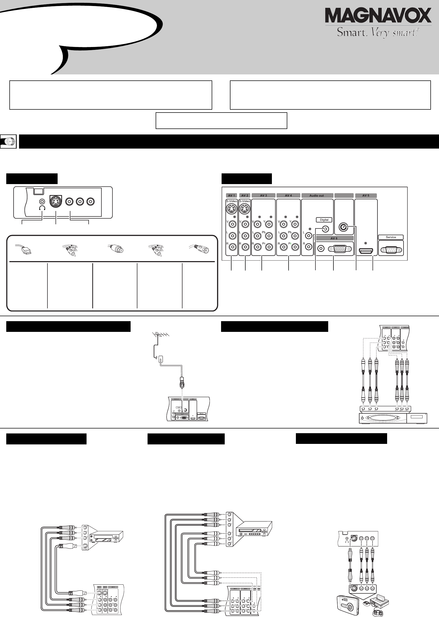
Antenna in
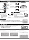
Your TV is designed to accept and display a wide range of video programs and signal sources,including VCRs, DVD players, high definition (HD) TV devices,
video game consoles, and regular TV broadcasts. These are a sample of devices that can be connected to the TV's front and rear panel connectors.
To view High Definition local broadcasts, connect
your outdoor or indoor antenna to the Antenna In
input on the rear panel. To view Analog Cable,
connect your Cable TV to the Antenna In input on
the rear panel.
Refer to the illustration for the
location of the Antenna In input.
Connect a set-top box (cable or satellite) to the TV
as follows:
S-Video
Video
L
R
Headphones Camera Game console
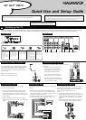
Quick-Use and Setup Guide
50" DLP™ HDTV
WARNING: TO PREVENT FIRE OR SHOCK HAZARD DO NOT
EXPOSE THIS UNIT TO RAIN OR EXCESSIVE MOISTURE.
IMPORTANT
This owner's manual is used with several different television models. Not all features (and
drawings) discussed in this manual will necessarily match those found with your television set.
This is normal and does not require that you contact your dealer or request service.
MAGNAVOX representatives are ready to help you with any questions about your new product.
Call us at 1-800-705-2000 or visit us on the web at WWW.MAGNAVOX.COM.
AmplifierVCR PVR PC Antenna in HDMI deviceSet-top box DVD
Hooking up the TV
Hooking up cable TV/antenna
Front panel Back panel
Connecting a set-top box
1. Connect the video output of the
set-top box to the component
video (YPbPr) connectors of the
AV3 input using RCA cables.
Note: You can also connect the
video output to the V connector.
2. Connect the audio output (L/R) of
the set-top box to the audio jacks
(L/R) using RCA cables.
Connecting a VCR Connecting a DVD
Connecting a camera
Follow these instructions to connect a VCR
(Video Cassette Recorder).
1. Connect the video output of the VCR to the
V connector of the AV1 input using an RCA
cable. Alternatively, you can also connect it to
the S-video connector of the AV1 input using an
S-video cable.
2. Connect the audio output (L/R) of the VCR to
the audio jacks (L/R) of the AV1 input using RCA
cables.
Use the following procedure to connect a DVD player
to the TV.
Connect the video output of the DVD player to
the V connector of the AV4 input using an RCA
cable. Alternatively, you can also connect it to the
component (YPbPr) connectors.
2. Connect the audio output (L/R) of the DVD player
to the audio jacks (L/R) using RCA cables
To connect a camera to the TV, you can use the
AV connectors located on the front connector
panel (AV7). Alternatively, you can also use the
AV connectors located on the rear
panel.
1. Connect the video output of the camera to
the S-video connector on the front panel using
an S-video cable. Alternatively, you can also
connect it to the V connector using an RCA
cable.
2. Connect the audio output (L/R) of the camera
to the audio jacks (L/R) using RCA cables.
S-Video
S-Video
Video
Video
L
R
LR
Antenna in
1.
HDMI
High-definition
Multimedia Interface
provides an
uncompressed,
all-digital audio/video
connection. HDMI
provides the ultimate
connection.
Component Video
Provides superior
picture quality by
separating the green,
blue, and red luminance
signals. Typically used
with red/white audio
cables.
S-Video
Supplies a better picture
than RF and Composite
connections. Used with
red/white audio cables.
Composite Audio/Video
Separate video (yellow)
and audio (red/white)
cables that provide a
basic connection from
the cable box or other
devices.
Note: The color of audio
inputs may differ, e.g.
red/white or red/black.
RF
Provides a basic
connection for
antenna or cable.
Provides both
audio and video.
Connection Basics
Best Better Good Basic Basic