


PELLERIN MILNOR CORPORATION
BICWUT01 (Published) Book specs- Dates: 20050118 / 20050118 / 20050118 Lang: ENG01 Applic: CWU
Troubleshooting Basket Speed Errors on Single-motor Washer-
extractors
This document describes the proper procedure for troubleshooting errors related to basket motor
speed on machines equipped with a single motor, an inverter, and a digital-to-analog (D-to-A)
board.
1. As the basket rotates, a photoeye sees each spoke of the main drive pulley. The photoeye
sends a pulse representing each pulley spoke to an input/output board (I/O #1).
2. I/O #1 determines the time between pulses and communicates this to the machine processor
board.
3. The processor board calculate the RPM and compares this value to the digital value
corresponding to the programmed basket speed. If the speed is incorrect, the processor board
signals the digital-to-analog (D-to-A) board to slightly increase or decrease the basket speed.
4. The D-to-A board converts the digital signal from the processor board to an analog voltage of
0 to 10 volts and sends it to the inverter. The speed at which the inverter drives the motor is
directly related to the voltage output of the D-to-A board.
5. The inverter interprets the voltage from the D-to-A board and adjusts the voltage and
frequency of the motor supply to drive the motor at a different speed.
6. The motor speed changes, causing the spokes on the main pulley to pass the photoeye at a
different rate, and the speed control circuit is complete.
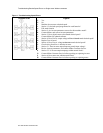
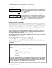
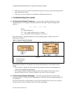
The most common indicator of a problem somewhere in the speed control circuit is that the
basket does not turn at the desired speed, or does not turn at all. The chart in Figure 1
describes the overview of the troubleshooting process.
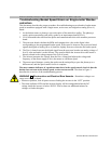
WARNING 1 : Electrocution and Electrical Burn Hazards—Hazardous voltages can
cause sever injury or death.
• Whenever possible, lock all power sources feeding the inverter in the “OFF” position.
• The status indicator LEDs and the inverter display will be extinguished when the DC
voltage inside the inverter is below 50VDC. Wait at least one additional minute for
voltages to further dissipate.