


SCC-LP Series Lowpass Filter Modules User Guide 4 ni.com
Device Specific Information
Note For general SCC module installation and signal connection information, and
information about the SC-2350 carrier, refer to the SCC Quick Start Guide, available
for download at
ni.com/manuals.
Installing the Module
Caution Refer to the Read Me First: Safety and Radio-Frequency Interference document
before removing equipment covers or connecting/disconnecting any signal wires.
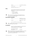
You can plug the SCC-LPXX into any analog input socket on the SC-2345.
It can function as a single-stage module or as the first or the second stage
of a dual-stage signal conditioning configuration. The socket you choose
determines which E Series DAQ device channels receive the SCC-LPXX
output signals, as explained in the Connecting the Input Signals section.
For single-stage conditioning, plug the SCC-LPXX into any socket J(X+1),
where X is 0 to 7, and connect the input signals to the module as described
in the Connecting the Input Signals section.
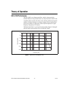
The SCC-LPXX can function as either the first or the second stage of a
dual-stage configuration. Plug the first-stage SCC into any socket J(X+9)
and plug the second-stage SCC into socket J(X+1), where X is 0 to 7.
Connect the input signals to the first-stage SCC. The SC-2345 connects the
output signals of the first-stage SCC to the inputs of the second-stage SCC.
An example of dual-stage conditioning is an SCC-A10 voltage attenuator
module followed by an SCC-LPXX.
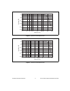
Sockets J9 to J16 also are available for digital input/output (DIO)
conditioning or control. Refer to the SC-2345 User Manual and SCC Quick
Start Guide for more information on configuring, connecting, and
installing SCC modules.
Connecting the Input Signals
Note The signal names have changed. Refer to ni.com/info and enter rdtntg to
confirm the signal names.
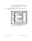
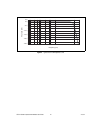
Each screw terminal is labeled by pin number <1..4>. Pins 1 and 2 form
a differential channel routed to E Series DAQ device channel X+8, and
pins 3 and 4 form a second differential channel routed to E Series DAQ
device channel X, where X is 0 to 7 depending on the socket where you plug
in the SCC-LPXX.