


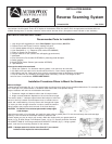


The Model AS-RS (Reverse Scanning System) reads ultrasonic signals that are projected from sensors mounted in your vehicle’s
rear bumper. As the signals “Echo” off of objects in the detection field, the control unit’s microprocessor translates them into
audible warning tones, or sounds, inside the vehicle which alert the driver. (An optional visual indicator is also available).
INSTALLATION INSTRUCTIONS
Recommended Tools for Installation
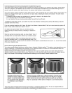
1. High torque drill suggested for use at Slow Speed of approximately 400 RPM
2. Grease Pencil and Center Punch for marking drill point
3. 1/8” carbide-tipped drill bit for starting pilot hole (optional)
4. Hole Saw 28mm (1.1") -*Required (Part number AS-28MMHS)
5. Pliers for Scotch-Lok Connectors
6. Phillips head bit for drill (used to set self-tapping ground screw)
7. Multimeter
8. Zinc Galvanizer (Part number AS-RPMB) for protecting metal bumpers
9. Safety goggles
10. Angle Gauge Sleeve Selector (part number AS-SSAG)
11. Tape Measure
You may also wish to have on hand:
1. Panel tool (Optional - for situations requiring plastic, inner panels to be removed)
2. 3/8 Split Loom (use split loom to shroud sensor wires for a more factory appearance)
3. Wire pulling tool (for routing wires from vehicle’s underside through to passenger compartment)
4. Rat-Tail metal file (for smoothing hole edges when necessary)- DO NOT use fingers to test
holes for burrs or smoothness. EDGES ARE SHARP!
Installation Procedures-Where to Mount the Sensors
Before You Begin:
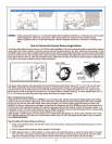
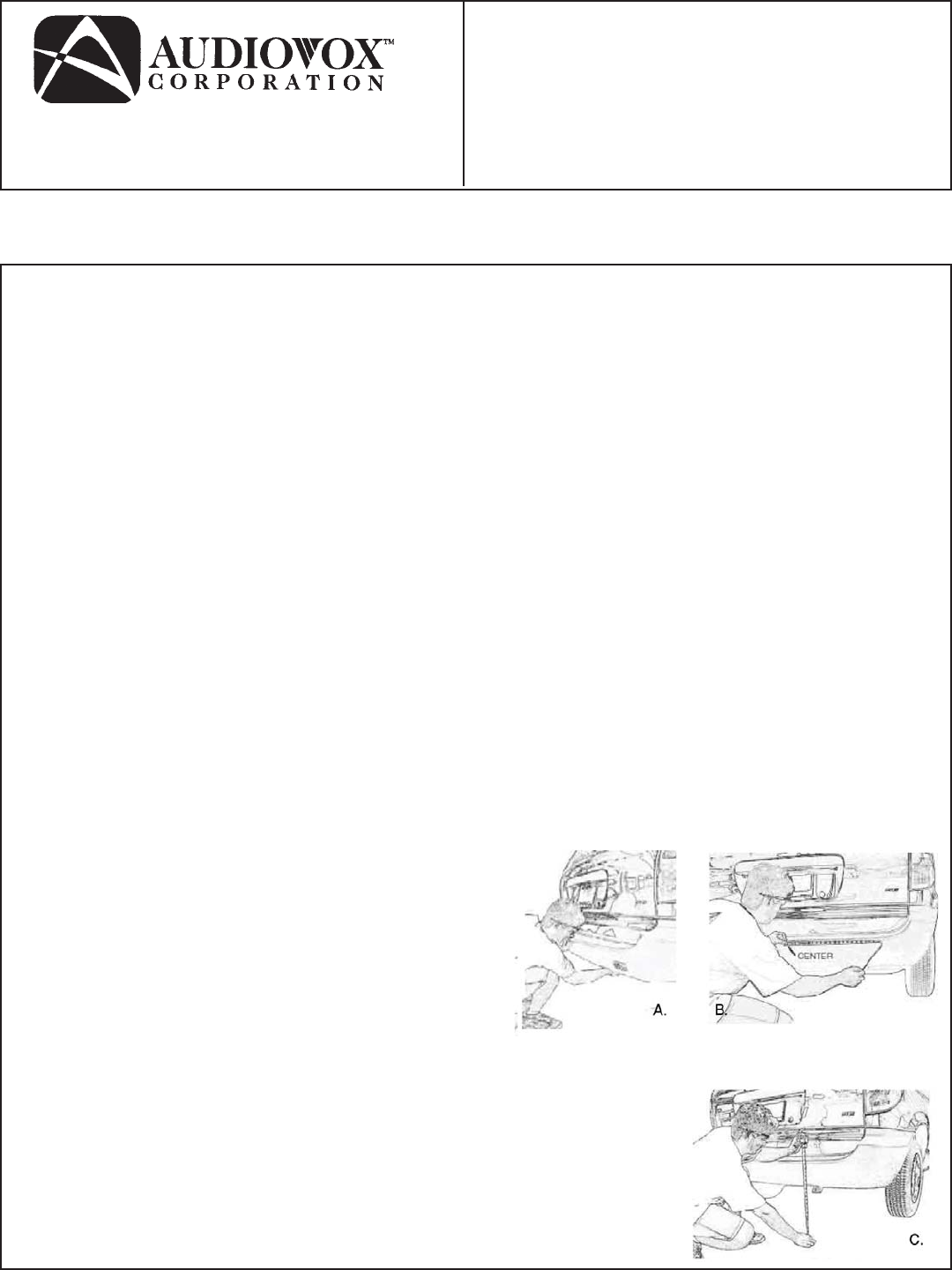
Inspect behind the bumper (fig. A.) in the approximate mounting area to check for any possible obstructions. For example check
for 5 miles per hour collision struts or hardened metal braces that could prohibit drilling.
Proper installation will take into consideration two factors:
1. Placement: height and distance either side of bumper center.
2. Angle: accurate detection depends on the correct sensor angle.
The sensor needs 1" clearance space behind the bumper to allow the
sensor to be fully inserted. Some bumpers have an outside cover or
fascia and a metal backing. You may have to drill through both layers
to insure you have enough clearance in order to install the sensors.
Other bumpers may require some removal of the foam backing.
CAUTION: Be Careful of hot exhaust parts and/or sharp edges
under bumper.
Determine the center of your bumper and mark the center using a grease pencil. Do not mount directly above exhaust pipe
opening. From the center of the bumper measure outward to the
location where you plan to mount your sensors. Mark the location with your grease pencil as
shown in Fig. B. Ideal Range From Bumper Center: 14" to 18". Sensors should be mounted
NO LOWER THAN 18" from the ground and NO HIGHER THAN 30’ (fig. C.). Using a grease
pencil, mark the final mounting location for the sensors.
NOTE: If bumper material is thicker than 5mm (0.2"), an external
bracket will be required to mount the sensors.
AS-RS
Reverse Scanning System
INSTALLATION MANUAL
FOR
Printed In USA 128-7073A
-1-