


10 Maytag Co. 113489-5 (W10185535)
Electrical Information _________________
Electrical Requirements
All electrical connections must be made by a properly licensed
and competent electrician. This is to ensure that the electrical
installation is adequate and conforms to local, state, and
national regulations or codes of the country of destination. In
the absence of such codes, all electrical connections,
materials, and workmanship must conform to the applicable
requirements of the National Electrical Code ANSI/NFPA NO.
70-LATEST EDITION or in Canada, the Canadian Electrical
Codes Parts 1 & 2 CSA C22.1-1990 or LATEST EDITION.
For personal safety, the dryer must be electrically grounded
in accordance with local codes and/or the National Electrical
Code ANSI/NFPA NO. 70-LATEST EDITION or in Canada, the
Canadian Electrical Codes Parts 1 & 2 CSA C22.1-1990 or
LATEST EDITION.
IMPORTANT: Failure to comply with these codes or
ordinances, and/or the requirements stipulated in this
manual can result in personal injury or component failure.
NOTE: Component failure due to improper installation will
void the warranty.
Each pocket should be connected to an independently
protected branch circuit. The dryer must be connected with
copper wire only. Do not use aluminum wire. The copper
conductor wire/cable must be of proper ampacity and
insulation in accordance with electric codes for making all
service connections.
NOTE: The use of aluminum wire will void the warranty.
An individual ground circuit must be provided to each
pocket, do not daisy chain.
Component failure due to improper voltage application will
void the warranty.
The manufacturer reserves the right to make changes in
specifications at any time without notice or obligation.
IMPORTANT: A separate protected circuit must be
provided to each pocket.
It is necessary to have a power disconnect for each pocket.
These disconnects must be located within 30 feet (9
meters) of the dryer and also be identified as being one of
two power sources supplying a dryer.
The dryer must be connected to the electric supply shown
on the data label.
Electrical Service Specifications
Grounding
A ground (earth) connection must be provided and installed
in accordance with local, state, and national regulations or
codes of the country of destination. In the absence of these
codes, grounding must conform to applicable requirements
of the National Electrical Code ANSI/NFPA NO. 70-LATEST
EDITION, or in Canada, the installation must conform to
applicable Canada Standards: Canadian Electrical Codes
Parts 1 & 2 CSA C22.1-1990 or LATEST EDITION. The ground
connection may be to a proven earth ground at the location
service panel.
Electrical Connections
If local codes permit, power to the dryer can be made by the
use of a flexible UL listed power cord/pigtail (wire size must
conform to rating of dryer), or the dryer can be hard wired
directly to the service breaker panel. In both cases, a strain
relief must be installed where the wiring enters the dryer.
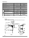
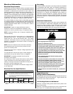
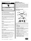
ELECTRICAL SERVICE SPECIFICATIONS (PER POCKET)
NOTES: A.
B.
When fuses are used they must be dual element, time delay, current limiting, class
RK1 or RK5 ONLY. Calculate/determine correct fuse value, by applying either local
and/or National Electrical Codes to listed appliance amp draw data.
Circuit breakers are thermal-magnetic (industrial) motor curve type ONLY. For
others, calculate/verify correct breaker size according to appliance amp draw rating
and type of breaker used.
SERVICE
VOLTAGE
PHASE
WIRE
SERVICE
APPROX.
AMP DRAW
MINIMUM
WIRE SIZE*
CIRCUIT
BREAKER
60 Hz 50 Hz
120 1ø 2 12 — 14 15
Single-Phase (1ø)
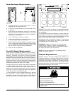
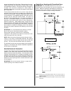
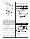
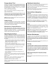
Wiring Connections/Hookup
The electrical input connections are made into the rear service
box located at the top rear of the dryer. To gain access, the
service box cover must be removed.
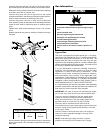
120 Volt Application with Neutral
Remove 3 screws holding down electrical box plate at the
top of the machine.
Remove 2 knockouts provided just in front of electrical box
and insert 3/4” UL listed strain relief into the holes.
* AWG standard type wire ... for individual lengths less than 100 feet (30.48
meters). 9/18/08
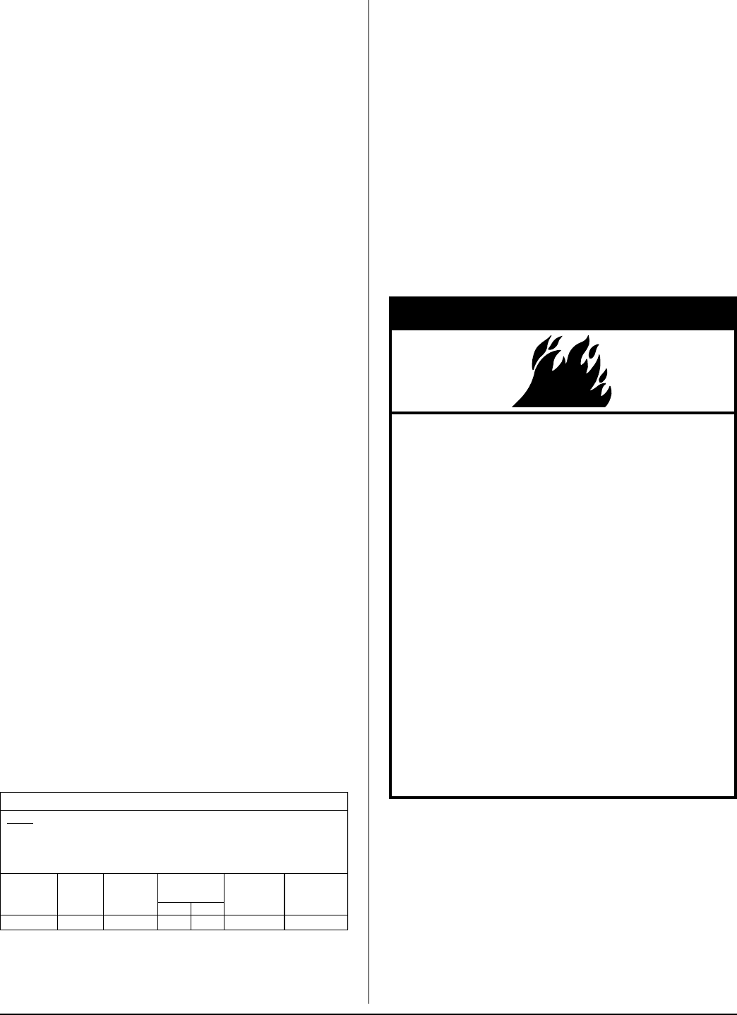
Fire Hazard
Use 10 gauge solid copper wire.
Use a UL listed strain relief.
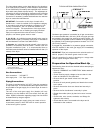
Determine the top pocket electrical connections by
checking wire label, which will be marked “top”.
Connect the top pocket white wire to the white wire
from the top pocket 15-amp service; Connect the
top pocket black wire to the black wire from the top
pocket 15-amp service; Connect the top pocket
green wire to the green wire from the top pocket
ground connection.
The remaining wires will be the bottom pocket
connect as follows:
Connect the bottom pocket white wire to the white
wire from the bottom pocket 15-amp service;
Connect the bottom pocket black wire to the black
wire from the bottom pocket 15-amp service;
Connect the bottom pocket green wire to the green
wire from the bottom pocket ground connection.
Securely tighten all electrical connections.
Failure to do so can result in death, fire, or electrical
shock.
▲ WARNING
!