


34
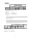
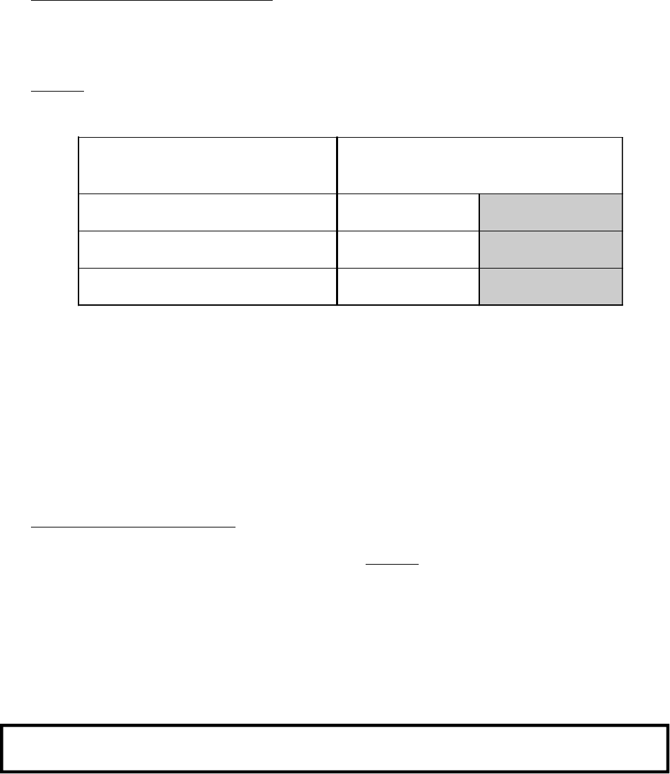
COMPRESSED AIR SUPPLY AIR PRESSURE
Normal 80 PSI 5.52 bars
Minimum Supply 70 PSI 4.83 bars
Maximum Supply 90 PSI 6.21 bars
Shaded areas are stated in metric equivalents
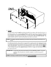
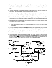
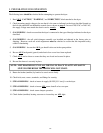
4. Steam Damper Air System Connections
The dryer is manufactured with a pneumatic (piston) damper system, which requires an external supply of
compressed air. The air connection is made to the steam damper solenoid valve which is located at the rear
inner top area of the dryer just above the electric service relay box (refer to the bottom illustration on
page 35).
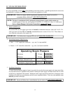
a. Air Requirements
b. Air Connection
Air connection to system --- 1/8-inch N.P.T.
c. No air regulation or filtration is provided with the dryer. External regulation/filtration of 80 PSI (5.51
bars) must be provided. It is suggested that a regulator/filter gauge arrangement be added to the
compressed air line just before the dryer connection. This is necessary to insure that correct and clean
air pressure is achieved.
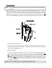
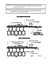
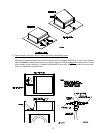
5. Steam Damper System Operation
The steam damper, as shown in the top illustration on page 35, allows the coil to stay constantly charged
eliminating repeated expansion and contraction. When the damper is opened, the air immediately passes
through the already hot coil, providing instant heat to start the drying process. When the damper is closed,
ambient air is drawn directly into the basket (tumbler), allowing a rapid cool down.
Diagram 1 -- shows the damper in the heating (open) mode, allowing heat into the basket (tumbler).
Diagram 2 -- shows the damper in the cool down (closed) mode, pulling ambient air directly into the basket
(tumbler) without passing through the coils.
NOTE: With the dryer off or with no air supply, the damper is in the cool down mode as shown
in Diagram 2.